A new type of tailrace tunnel ventilation hole structure

A technology of tailrace tunnels and ventilation holes, which is applied in water conservancy projects, hydroelectric power generation, hydroelectric power stations, etc., can solve the problem that the minimum negative pressure and the maximum positive pressure cannot be well balanced, and achieve a remarkable effect and relieve the impact pressure. Effect

Active Publication Date: 2017-04-05
HOHAI UNIV
View PDF4 Cites 0 Cited by
  • Summary
  • Abstract
  • Description
  • Claims
  • Application Information

AI Technical Summary

Problems solved by technology

In the current design, the air hole area of ​​a fixed size is basically used, and the contradiction between the minimum negative pressure and the maximum positive pressure cannot be well balanced. The present invention uses a new air hole form, which is well coordinated Minimum negative pressure and instantaneous maximum positive pressure of tailrace tunnel

Method used


Image

  • A new type of tailrace tunnel ventilation hole structure
  • A new type of tailrace tunnel ventilation hole structure
  • A new type of tailrace tunnel ventilation hole structure

Examples


Embodiment

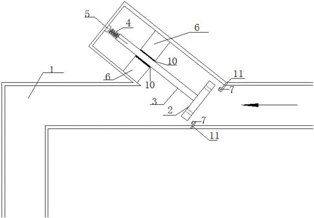
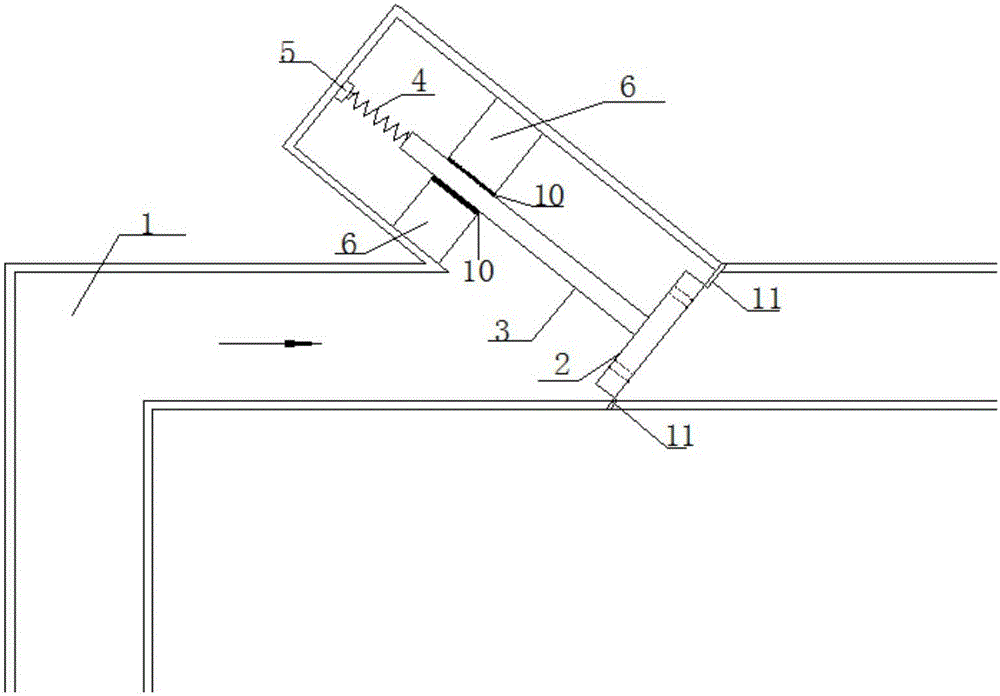
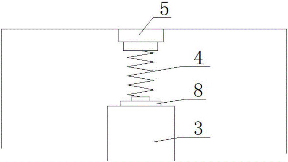
[0033] The novel tailrace tunnel ventilation orifice structure of this embodiment, such as figure 1 , figure 2 , image 3 , Figure 4 and Figure 5 As shown, when the movable baffle 2 is closed, the air flow can only pass through the reserved round hole 9 in the movable baffle 2, the movable connecting rod 3 is fixed with the movable baffle 2, and the annular anti-slip block body 6 is used to fix the movable connecting rod 3. direction. A movable baffle 2 is set at the ventilation hole 1. When the movable baffle 2 is opened, the movable connecting rod 3 slips sideways. A lubricating device 10 is arranged between the annular anti-slip block body 6 and the movable connecting rod 3. The spring buffer device 5 is used to protect The movable connecting rod 3, when the movable baffle 2 is pushed up by the air flow of the intake air, the movable connecting rod 3 moves accordingly, compressing the spring 4, at this time, the ventilation hole is full-area air intake; when the mova...


PUM


Abstract

The invention discloses a novel tailwater tunnel ventilation hole structure, which comprises a ventilation hole, a movable baffle, a movable connecting rod, a spring, a buffer device, an annular anti-slip block and a card slot. The ventilation hole is a two-way ventilation hole. When there is negative pressure in the tailwater tunnel, the gas enters the ventilation hole from the outside, and the airflow will push up the movable baffle, and the movable baffle will drive the movable connecting rod to move obliquely upward. The baffle is fully opened, the air intake area reaches the maximum, and the air supply speed is fast, which can relieve the negative pressure of the tailrace tunnel in time; when the tailrace tunnel is exhausted, the pressure of the reverse airflow will make the movable baffle move obliquely downward , the movable baffle is engaged with the card slot, the vent hole is tightly closed, and the airflow is discharged from the round hole reserved on the movable baffle, and the exhaust speed is relatively slow, which greatly reduces the transient pressure when the air mass is discharged from the orifice. On the premise of satisfying other safety and reliability performance requirements, the invention can greatly alleviate the negative pressure in the tunnel during air intake and the impact pressure during exhaust, especially for tailwater tunnels of hydropower stations and urban pipe networks, and the effect is remarkable.

Description

technical field [0001] The invention relates to the technical field of water conservancy and hydropower engineering, in particular to a novel tailwater tunnel ventilation hole structure, which is suitable for hydropower station tailwater tunnels and urban pipe networks. Background technique [0002] In the early stage of the construction of a large-scale diversion-type hydropower station, a large-scale construction diversion tunnel is required, and the design often combines the construction diversion tunnel with the tail water system of the hydropower station. In the later stage of the project, part of the diversion tunnel is converted into a power generation tail water tunnel. When the water level of the downstream cascade reservoirs is close to the top of the tunnel, the initial pressure in the tailrace tunnel is small. When the power station transitions, the pressure and surge in the tailrace change drastically, which may lead to the tailrace tunnel at a higher position. ...

Claims


Application Information

Patent Timeline
Patent Type & Authority Patents(China)
IPC IPC(8): E02B9/06
CPCE02B9/06Y02E10/20
Inventor 俞晓东张健储善鹏刘甲春陈胜
Owner HOHAI UNIV
Why Eureka
Try Eureka