Single-layer prefabricated assembly type reinforced concrete beam-column joint

A reinforced concrete and prefabricated assembly technology, which is applied in the direction of architecture and building construction, can solve the problems of high installation and positioning accuracy, large amount of additional support, and difficulty in ensuring the integrity of beam-column joints.

Inactive Publication Date: 2016-07-27
HARBIN INST OF TECH
View PDF7 Cites 45 Cited by
  • Summary
  • Abstract
  • Description
  • Claims
  • Application Information

AI Technical Summary

Problems solved by technology

[0003] The purpose of the present invention is to solve the problems that the integrity of beam-column joints in existing prefabricated reinforced concrete frame structures is difficult to guarantee, the installation and positioning accuracy of prefabricated columns and prefabricated beam components is high, and the additional support is large
Furthermore, a single-layer prefabricated reinforced concrete beam-column joint is provided

Method used


Image

  • Single-layer prefabricated assembly type reinforced concrete beam-column joint
  • Single-layer prefabricated assembly type reinforced concrete beam-column joint
  • Single-layer prefabricated assembly type reinforced concrete beam-column joint

Examples


specific Embodiment approach 1

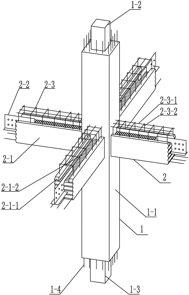
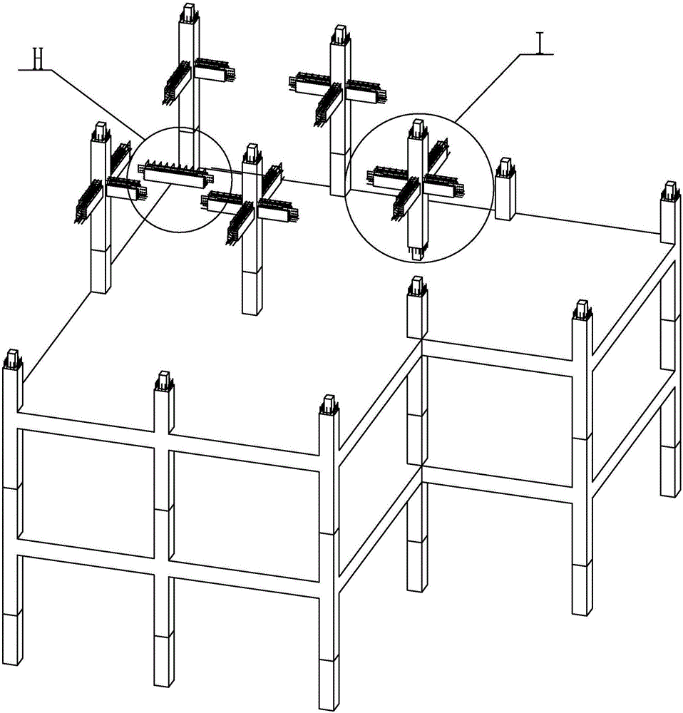
[0020] Specific implementation mode one: combine Figure 1 to Figure 11 Describe this embodiment, a single-layer prefabricated reinforced concrete beam-column node of this embodiment, which includes a vertical column section 1 and a plurality of node superimposed beam sections 2, the vertical column section 1 is a rectangular column section, and the vertical column section 1 is a rectangular column section. The straight column section 1 is divided into an upper column section and a lower column section. The column heights of the upper column section and the lower column section are respectively 1 / 2 of the storey height where they are located. Multiple node superimposed beam sections 2 are distributed in the rectangular column section. On the side, the lengths of multiple nodal superimposed beam sections 2 are 1 / 3 of the span of their respective beams, and the nodal superimposed beam sections 2 are integrated with the vertical column section 1, and each nodal superimposed beam s...

specific Embodiment approach 2

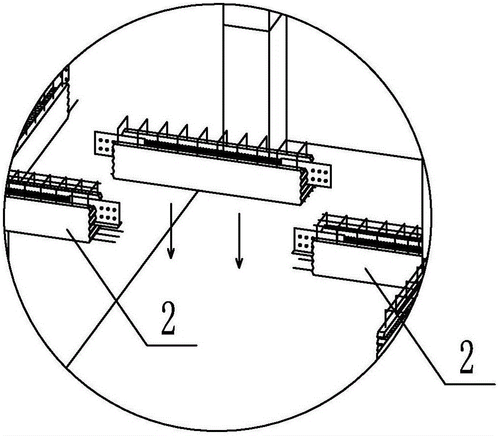
[0021] Specific implementation mode two: combination figure 1 To illustrate this embodiment, the trough-shaped pouring section 2-1 of each node superimposed beam section 2 of this embodiment also includes a floor support platform 2-1-1 and a beam section occlusal groove 2-1-2, and the floor support platform 2 -1-1 is used for the placement of laminated slabs, and the beam segment occlusal groove 2-1-2 is used for occlusal secondary pouring of concrete. The concrete poured for the second time of the beam section relies on the occlusal groove 2-1-2 of the beam section in the length direction, and relies on the inner wall of the floor support platform to resist the lateral slippage of the concrete in the occlusal groove 2-1-2 perpendicular to the length direction . The end of the trough-shaped pouring section 2-1 is in a triangular sawtooth shape. Other compositions and connections are the same as in the first embodiment.

specific Embodiment approach 3

[0022] Specific implementation mode three: combination figure 1 The present embodiment will be described. The meshing teeth of the present embodiment are triangular in shape. Such setting is convenient for realization. Other compositions and connections are the same as those in Embodiment 1 or Embodiment 2.


PUM


Abstract

The invention relates to a prefabricated reinforced concrete beam-column joint, in particular to a single-layer prefabricated assembly type reinforced concrete beam-column joint. In order to solve the problem that the connection integrity of existing prefabricated beams and prefabricated columns is hard to guarantee, the prefabricated joint for one-piece casting manufacturing of a column section and part of beam sections is provided according to the concept of the point of inflection. The single-layer prefabricated assembly type reinforced concrete beam-column joint is formed by overall manufacturing of a vertical column section (1) and joint superposed beam sections (2) in a factory for prefabrication. A manufacturing method comprises the steps of beam-column longitudinal bar and stirrup binding, connector pre-burying, formwork erecting and concrete pouring and curing. The height of the vertical column section (1) of the joint is 1/2 of the storey height, and the length of each joint superposed beam section (2) is 1/3 of the span of adjacent columns. The vertical column section (1) comprises a pouring section (1-1), a concrete filled steel tube connector (1-2), a steel tube connector (1-3) and column section longitudinal bars (1-4). Each joint superposed beam section (2) comprises a groove-shaped pouring section (2-1), inverted-T-shaped structural steel connectors (2-2) and a reinforcement cage framework (2-3). The single-layer prefabricated assembly type reinforced concrete beam-column joint is applied to the construction industry.

Description

technical field [0001] The invention relates to a building structure component, in particular to a single-layer prefabricated reinforced concrete beam-column joint. Background technique [0002] The prefabricated concrete structure is a concrete structure made of prefabricated components as the main force-bearing components and connected by assembly. Prefabricated concrete structures have been widely used at home and abroad because of their advantages such as good product quality, high production efficiency, and good environmental benefits. At present, the prefabricated concrete structure system adopts the method that the beams and columns are prefabricated in the factory, and the connection between the beams and the columns is poured twice on site. This method has the following problems: 1. The concrete at the connection position between the prefabricated beams and the prefabricated columns needs to be poured on site. The pouring quality is poorer than that of factory pour...

Claims


Application Information

Patent Timeline
Patent Type & Authority Applications(China)
IPC IPC(8): E04B1/20E04B1/58
CPCE04B1/20E04B1/58
Inventor 刘昌永杨理贵袁长春
Owner HARBIN INST OF TECH
Why Eureka
Try Eureka