Overlap type large-displacement diaphragm compressor

A diaphragm compressor, large displacement technology, applied in the direction of liquid displacement machinery, mechanical equipment, variable displacement pump components, etc., can solve the problems of easy damage, increased production cost and difficulty, and heavy weight

Active Publication Date: 2016-07-27
包头盈德气体有限公司
View PDF9 Cites 8 Cited by
  • Summary
  • Abstract
  • Description
  • Claims
  • Application Information

AI Technical Summary

Problems solved by technology

[0002] The compression part of a traditional diaphragm compressor is mainly composed of a cylinder block, an oil distribution plate, a diaphragm, and a cylinder head. The air inlet and air outlet of the air cavity are set on the end face of the cover. The cylinder block and the cylinder head must bear high pressure, so they are relatively thick and heavy. To make a compressor with a large displacement, the cylinder block and the oil distribution plate are usually enlarged. , the diameter of the diaphragm and the cylinder head, in a container with the same pressure, the larger the diameter, the greater the thickness, the more cumbersome the whole machine, and the higher the production cost and difficulty
[0003] In addition, in the existing diaphragm compressors, the curved surface cavity is divided into a high-pressure air cavity and a high-pressure oil cavity by the diaphragm. The oil distribution plate on the oil cavity side is provided with oil guide holes, and the cylinder head on the air cavity side is provided with air inlet and outlet holes. Due to the pressure difference between the two ends of the oil and gas, the diaphragm will often produce an impact force when it contacts the hole when it reciprocates. Chip position is particularly vulnerable to damage

Method used


Image

  • Overlap type large-displacement diaphragm compressor
  • Overlap type large-displacement diaphragm compressor

Examples


Embodiment Construction

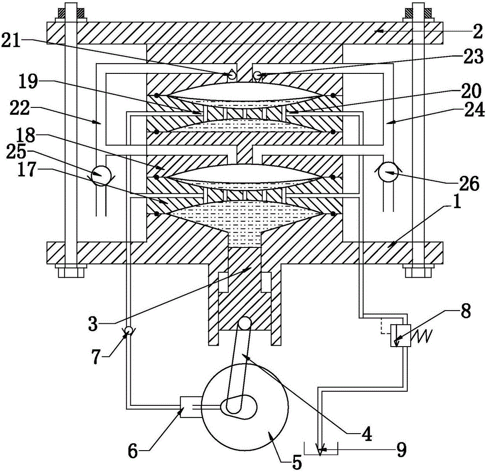
[0014] The superimposed large-displacement diaphragm compressor of the present invention will be further described in detail below in conjunction with the accompanying drawings and specific embodiments.

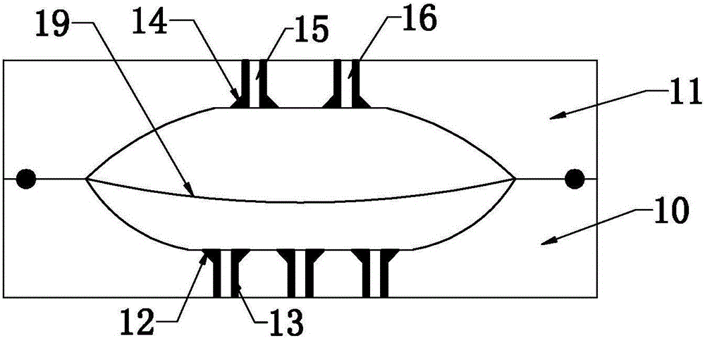
[0015] As shown in the figure, the superimposed large-displacement diaphragm compressor of the present invention includes a cylinder body 1, a cylinder head 2 installed on the cylinder body, and at least two groups of mutual Superimposed compression mechanisms. In this embodiment, there are two sets of compression mechanisms superimposed on each other. The cylinder body 1 and the cylinder head 2 are fixedly connected by fasteners and the compression mechanisms are pressed therein. Each set of compression mechanisms includes a component For the set oil distribution plate 17 and air distribution plate 18, a diaphragm 19 is arranged between each pair of oil distribution plate 17 and air distribution plate 18, and the side of the diaphragm 19 near the oil distribution plate is the...


PUM


Abstract

The invention discloses an overlap type large-displacement diaphragm compressor. The overlap type large-displacement diaphragm compressor comprises a cylinder body and a cylinder cover installed on the cylinder body. At least two sets of compressing mechanisms which are mutually overlapped are arranged in the cylinder body. Each set of compressing mechanism comprises oil distribution discs and gas distribution discs. A diaphragm is arranged between the oil distribution disc and the gas distribution disc in each pair. A piston is arranged in the cylinder body. The power end of the piston is connected with a flywheel through a crank-link mechanism. An oil supply plunger pump is arranged on one side of the flywheel. Each oil distribution disc is provided with an oil supply inlet and an overpressure overflow hole. The oil supply plunger pump is connected to the oil supply inlets. Outlets of the overpressure overflow holes are connected with an oil tank. The gas distribution discs are provided with gas inlets and gas outlets. By the adoption of the structure, the thickness of the gas distribution discs and the thickness of the oil distribution discs can be decreased, and the overlap type large-displacement diaphragm compressor has a positive effect on saving materials and lowering the machining difficulty; in addition, the production cost is further reduced by increasing or decreasing the overlap number; and the situation that the diaphragms corresponding to oil guide holes, the gas inlets and the gas outlets are damaged is avoided.

Description

technical field [0001] The invention relates to a diaphragm compressor, in particular to a superimposed large-displacement diaphragm compressor. Background technique [0002] The compression part of a traditional diaphragm compressor is mainly composed of a cylinder block, an oil distribution plate, a diaphragm, and a cylinder head. The air inlet and air outlet of the air cavity are set on the end face of the cover. The cylinder block and the cylinder head must bear high pressure, so they are relatively thick and heavy. To make a compressor with a large displacement, the cylinder block and the oil distribution plate are usually enlarged. , Diaphragm, and the diameter of the cylinder head. For a container with the same pressure, the larger the diameter, the larger the thickness, the more bulky the whole machine, and the higher the production cost and difficulty. [0003] In addition, in the existing diaphragm compressors, the curved surface cavity is divided into a high-pres...

Claims


Application Information

Patent Timeline
Patent Type & Authority Applications(China)
IPC IPC(8): F04B45/053F04B39/00F04B39/12
CPCF04B39/00F04B39/122F04B39/125F04B45/0533
Inventor 夏铭宇夏致俊
Owner 包头盈德气体有限公司
Why Eureka
Try Eureka