
Inductive thermal image nondestructive testing device based on commensal type magnet yoke coil

A yoke coil and non-destructive testing technology, which is applied in the field of induction thermal imaging non-destructive testing devices, can solve the problems of small magnetic induction intensity, small detectable area, low defect detection efficiency, etc., so as to improve temperature contrast and improve defect detection. The effect of efficiency

Active Publication Date: 2016-08-03
UNIV OF ELECTRONIC SCI & TECH OF CHINA
View PDF10 Cites 10 Cited by
  • Summary
  • Abstract
  • Description
  • Claims
  • Application Information

AI Technical Summary

Problems solved by technology

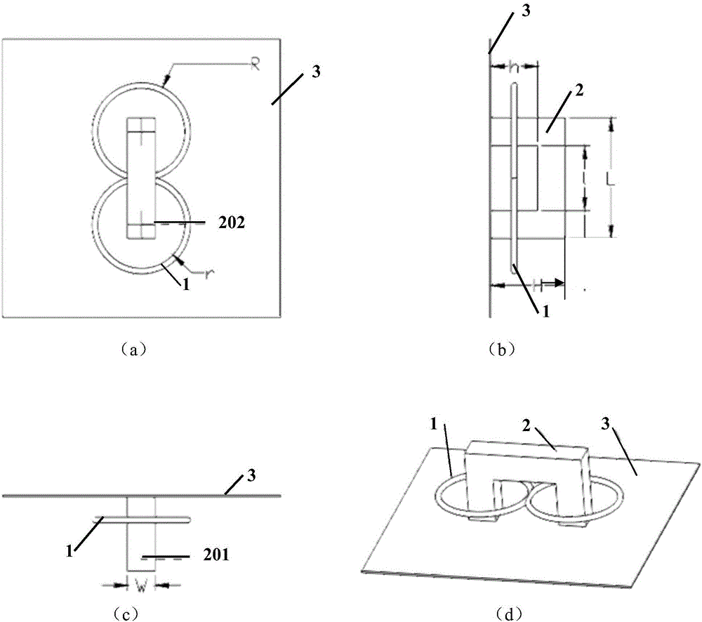
[0004] At present, the coils used in ECPT detection technology include straight wire coils, rectangular coils, circular coils, etc., and their structural characteristics are as follows: figure 2 As shown, the straight wire coil is usually better, but these three types of coils have the following disadvantages in the detection process: the utilization rate of the alternating magnetic field generated by the excitation coil is extremely low, and the magnetic field generated by the excitation in the conductor specimen is not good enough. Uniform and low magnetic induction intensity, low thermal contrast between defective areas and non-defective areas in the thermal image collected by the infrared thermal imager, low thermal contrast between defect areas and non-defective areas, small single detectable area, and insensitivity to specific inclination angle defects, etc., make defect detection Low efficiency

Method used


Image

  • Inductive thermal image nondestructive testing device based on commensal type magnet yoke coil
  • Inductive thermal image nondestructive testing device based on commensal type magnet yoke coil
  • Inductive thermal image nondestructive testing device based on commensal type magnet yoke coil

Examples


Embodiment Construction

[0025] Specific embodiments of the present invention will be described below in conjunction with the accompanying drawings, so that those skilled in the art can better understand the present invention. It should be noted that in the following description, when detailed descriptions of known functions and designs may dilute the main content of the present invention, these descriptions will be omitted here.

[0026] image 3 It is a structural diagram of a specific embodiment of the novel symbiotic yoke coil adopted in the present invention. In this example, if image 3 As shown, the symbiotic yoke coil in the present invention includes a "冂" shaped yoke 2 and an excitation coil 1 .

[0027] The excitation coil 1 is composed of two equivalent toroidal coils, and the two equivalent toroidal coils are cross-connected in a figure of eight, and the winding direction is type, and the magnetic fields generated by the two equivalent toroidal coils strengthen each other, which is th...


PUM


Abstract

The invention discloses an inductive thermal image nondestructive testing device based on a commensal type magnet yoke coil.On the basis of the prior art, a coil generating an alternating magnetic field is improved, and in other words, the brand-new commensal type magnet yoke coil is adopted to replace a traditional straight wire coil, a rectangular coil and a circular coil to generate the alternating magnetic field.Due to the fact that the relative permeability of a magnet yoke is much higher than that of air, the magnet yoke can efficiently 'collect' a magnetic field excited by an exciting coil in a space and 'inject' the magnetic field into a conductor test piece.In other words, by means of the commensal type magnet yoke coil, a magnetic field higher in intensity can be excited in the conductor test piece through the alternating magnetic field excited by the exciting coil more efficiently, furthermore a vortex filed which is larger in area and uniform is generated to heat the conductor test piece, the temperature contrast ratio of a defective area and a non-defective area in a heat map is effectively raised, and the purpose of improving the efficiency of detecting defects is finally achieved.

Description

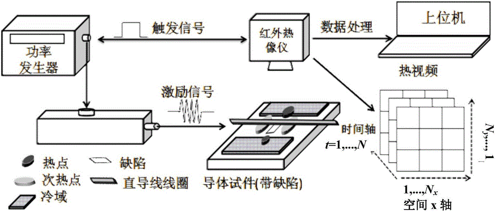
technical field [0001] The invention belongs to the technical field of nondestructive testing, and more specifically relates to an induction thermal imaging nondestructive testing device based on a symbiotic yoke coil. Background technique [0002] Non-destructive testing technology is an important means to control product quality and ensure the safe operation of in-service equipment. Eddy Current Pulsed Thermography (ECPT for short) is a non-destructive testing technology formed by combining eddy current and thermal imaging, which can realize the rapid detection of defects in a wide range of different depths. It has become an important means to analyze the failure reasons of conductor materials. [0003] The principle of ECPT detection technology is as follows: figure 1 As shown, the trigger signal turns on the infrared thermal imager and the power generator at the same time, when the alternating excitation current (excitation signal) generated and output by the power gen...

Claims


Application Information

Patent Timeline
IPC IPC(8): G01N25/72
CPCG01N25/72
Inventor 高斌赵健田贵云
Owner UNIV OF ELECTRONIC SCI & TECH OF CHINA
Learn More