Seabed high-voltage power cable and manufacture method for same

A high-voltage power and cable technology, which is applied in submarine cables, cable/conductor manufacturing, power cables with shielding layers/conductive layers, etc., can solve the problems of waste of resources, large redundancy of armor layers, etc.

Inactive Publication Date: 2016-08-03
沈群华
View PDF10 Cites 2 Cited by
  • Summary
  • Abstract
  • Description
  • Claims
  • Application Information

AI Technical Summary

Problems solved by technology

[0008] However, after repeated tests, the applicant believes that there is still room for structural improvement in the prior art high-voltage cables for submarine use, which is mainly reflected in (1) excessive redundancy of the armor layer, mainly in terms of tensile strength. The main consideration in the existing technology is the roundness of the cable. Therefore, the reinforcement used in the armor layer far exceeds the required tensile strength, resulting in a waste of resources; (2) the wear resistance and anti-seepage of the outer protective layer The performance of water and seawater resistance needs to be improved; (3) The setting method of the shielding layer and the insulating layer can be further improved to better improve the performance of the cable; (4) The material of the insulating layer needs to be further developed so that it can achieve higher resistance pressure rating or performance

Method used


Image

  • Seabed high-voltage power cable and manufacture method for same
  • Seabed high-voltage power cable and manufacture method for same
  • Seabed high-voltage power cable and manufacture method for same

Examples


Embodiment 1

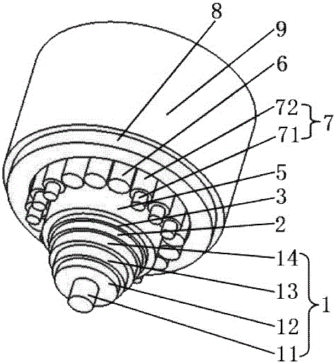
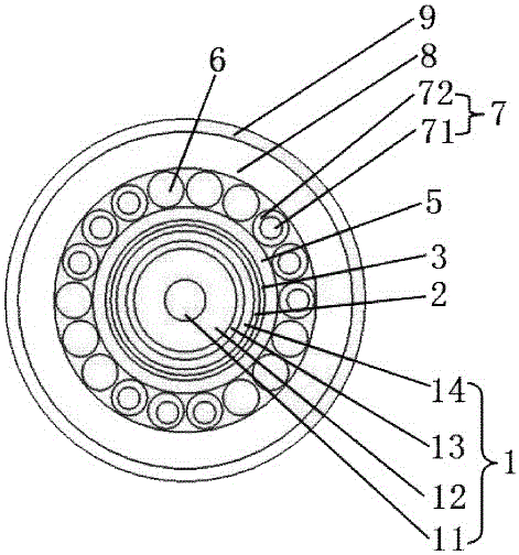
[0059] please see figure 1 and figure 2 , high-voltage power cable for seabed, characterized in that it is composed of conductive unit 1, metal shielding layer 2, water blocking layer 3, inner sheath 5, armored layer, outer sheath 8, outer sheath The cover protective layer 9 is formed; the conductive unit 1 is composed of a conductor 11, an insulating layer 12 coated outside the conductor by extrusion molding, an insulating shielding layer 13 located outside the insulating layer, and an insulating shielding layer coated outside the insulating shielding layer by extrusion molding. Conductor sheath 14 is formed, on any cross-section, the center of the conductor and the insulation layer coincide, and the diameter of the insulation layer is 1.5 to 5 times the diameter of the conductor and the minimum thickness of the insulation layer is 1.5mm; the armor The packing layer is composed of filling rope 6 and reinforcing member 7, and reinforcing member 7 is composed of reinforcing m...

Embodiment 2

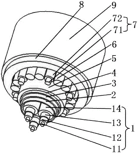
[0062] please see image 3 and Figure 4 , a high-voltage power cable for seabed, which is characterized in that it is composed of a metal shielding layer 2, a water blocking layer 3, an adhesive layer 4, an inner sheath 5, an armored layer, an outer sheath 8, an outer sheath, and The sheath protection layer 9 is composed of three conductive units 1 arranged in two or two phases in a circumscribed manner inside the metal shielding layer, and the three conductive units are inscribed with the metal shielding layer; The insulating layer 12 outside the conductor, the insulating shielding layer 13 located outside the insulating layer, and the conductor sheath 14 extruded and coated outside the insulating shielding layer are composed. On any cross-section, the center of the conductor and the center of the insulating layer overlap, and the diameter of the insulating layer is 1.5 to 5 times the diameter of the conductor and the minimum thickness of the insulating layer is 1.5mm; The...

Embodiment 3

[0064] please see Figure 5 and Figure 6 , a high-voltage power cable for submarine use, which is characterized in that it is composed of a metal shielding layer 2, a water blocking layer 3, an adhesive layer 4, an inner sheath 5, an armor layer, and an outer sheath 8, which are arranged in sequence from the inside to the outside. Inside the metal shielding layer are three conducting units 1 arranged in two-phase circumscribing, and the three conducting units are inscribed with the metal shielding layer; The insulating shielding layer 13 located outside the insulating layer and the conductor sheath 14 extruded and coated outside the insulating shielding layer are formed. In any cross-section, the center of the conductor coincides with the center of the insulating layer, and the insulating layer The diameter is 1.5 to 5 times of the conductor diameter and the minimum thickness of the insulating layer is 1.5mm; the armor layer is composed of a filling rope 6 and a reinforcemen...


PUM

PropertyMeasurementUnit
thicknessaaaaaaaaaa
densityaaaaaaaaaa
tensile strengthaaaaaaaaaa

Abstract

The invention belongs to the technical field of cables and especially relates to a seabed high-voltage power cable. The cable is composed of an electric conduction unit, a metal shielding layer, a waterproof layer, an inner sheath, an armor layer, an outer sheath and an outer sheath protective layer which are disposed successively from inside to outside, wherein the electric conduction unit is composed of a conductor, an insulating layer, an insulation shielding layer and a conductor protective layer, the circle center of the conductor and the circle center of the insulating layer coincide, the diameter of the insulating layer is 1.5-5 times of the diameter of the conductor, and the minimum thickness of the insulating layer is 1.5 mm; a filling rope group and a reinforcing part group are distributed outside the inner sheath alternately, and both the filling rope group and the reinforcing part group are tightly adhered to the inner sheath; the outer sheath protective layer is made of polyamide; and the insulating layer is made of silane cross-linking polyethylene; and the insulating layer is made of silane cross-linking polyethylene or a special material. The invention also discloses a manufacture method for the cable. The cable provided by the invention mainly has the beneficial effects that redundancy of mechanical performance is more proper; consumption of resources is reduced; the cable has higher wear resistance; the cable can be protected from water leakage and seawater; shielding performance is better; and the cable can even transmit high voltages.

Description

[0001] This application is a divisional application for an invention patent named: submarine high-voltage cable and its manufacturing method, with an application date of September 15, 2014, and an application number: 201510049118.8; the application for an invention patent with an application number: 201510049118.8 has been requested A divisional application for an invention patent named: submarine high-voltage cable and its manufacturing method, application date: September 15, 2014, and application number: 201410467691.6. technical field [0002] The invention belongs to the technical field of submarine cables, and in particular relates to a high-voltage power cable for a submarine and a manufacturing method thereof. Background technique [0003] The surface of the earth is divided into vast waters connected to each other by major continents called oceans. The total area of ​​the earth is about 360 million square kilometers, accounting for about 71% of the earth's surface...

Claims


Application Information

Patent Timeline
Patent Type & Authority Applications(China)
IPC IPC(8): H01B7/14H01B7/17H01B7/18H01B7/282H01B7/02H01B9/02H01B13/02H01B13/06H01B13/14H01B13/22H01B13/26H01B13/24H01B3/44
CPCY02A30/14H01B7/14H01B3/44H01B7/02H01B7/17H01B7/18H01B7/282H01B9/02H01B13/02H01B13/06H01B13/14H01B13/22H01B13/24H01B13/26
Inventor 沈群华
Owner 沈群华
Why Eureka
Try Eureka