Eureka AIR delivers breakthrough ideas for toughest innovation challenges, trusted by R&D personnel around the world.

Chip structure and manufacturing method thereof

A technology of chip structure and manufacturing method, applied in semiconductor/solid-state device manufacturing, electrical components, electric solid-state devices, etc., can solve problems such as broken pads 12, occupation of wafer area, and unusable chip structure, achieving increased The effect of quantity and quality assurance

Active Publication Date: 2016-08-03
SEMICON MFG INT (SHANGHAI) CORP
View PDF5 Cites 5 Cited by
  • Summary
  • Abstract
  • Description
  • Claims
  • Application Information

AI Technical Summary

Problems solved by technology

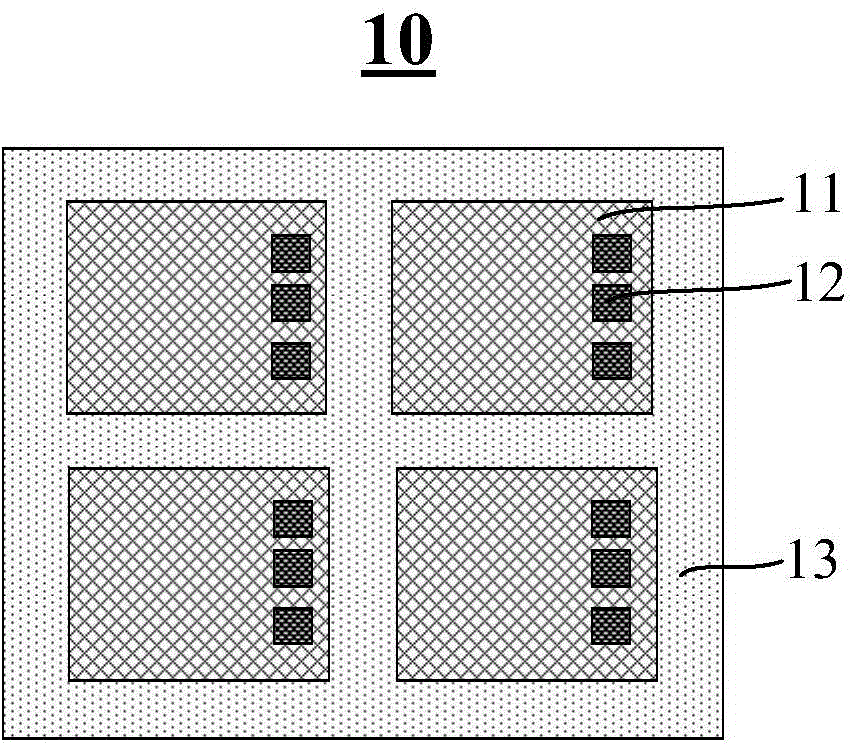
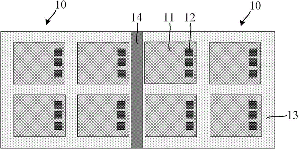
And as we all know, when carrying out CP test, it is very easy to damage the bonding pad 12, so that part of the effective area in the chip 11 loses its effect, reduces the number of useful chips 11, and affects the improvement of the production efficiency; and, because the chip structure 10 shares The dicing lane 14 cannot be utilized, and it occupies the area of ​​the wafer, which is not conducive to improving the utilization rate of the wafer

Method used


Image

  • Chip structure and manufacturing method thereof
  • Chip structure and manufacturing method thereof
  • Chip structure and manufacturing method thereof

Examples


Embodiment Construction

[0029] The chip structure of the present invention and its manufacturing method will be described in more detail below in conjunction with schematic diagrams, wherein a preferred embodiment of the present invention is shown, it should be understood that those skilled in the art can modify the present invention described here, and still realize the present invention beneficial effect. Therefore, the following description should be understood as the broad knowledge of those skilled in the art, but not as a limitation of the present invention.

[0030] In the interest of clarity, not all features of an actual implementation are described. In the following description, well-known functions and constructions are not described in detail since they would obscure the invention with unnecessary detail. It should be appreciated that in the development of any actual embodiment, numerous implementation details must be worked out to achieve the developer's specific goals, such as changing...


PUM


Abstract

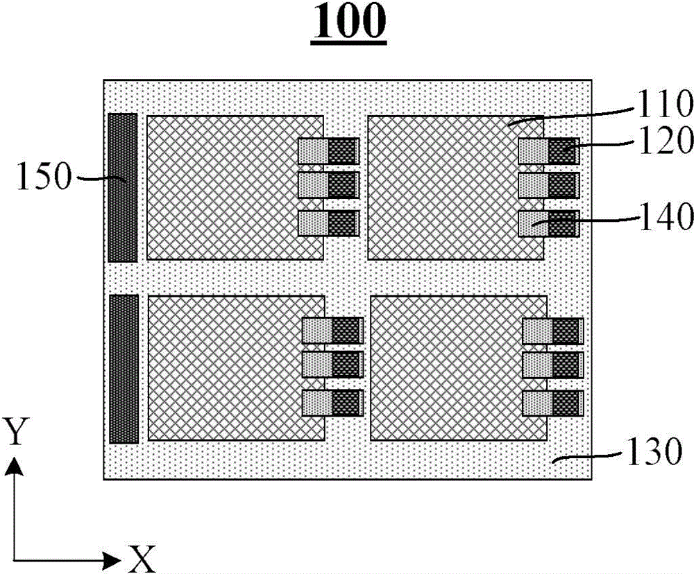
The invention provides a chip structure and a manufacturing method thereof. According to the invention, a welding pad is formed on a cutting channel at one side of a first direction of a chip and is connected with the chip through a metal connecting wire, a test probe is pricked into the welding pad located at the cutting channel when a CP test is carried out subsequently, and no damage is imposed on the chip, so that the quality of the chip can be ensured, and the number of available chips of a wafer is increased. In addition, subsequent cutting for the chip structure is not affected after the CP test is completed. Furthermore, the invention provides a manufacturing method of the chip structure. A photomask unit on the cutting channel at the other side of the first direction of the chip is set to be a dark portion, thereby avoiding secondary exposure for the public cutting channel, ensuring the performance of the welding pad on the public cutting channel, and enabling the CP test to be carried out smoothly.

Description

technical field [0001] The invention relates to the field of semiconductor manufacturing, in particular to a chip structure and a manufacturing method thereof. Background technique [0002] In semiconductor manufacturing, each wafer is composed of several chips, and a scribe lane (Scribelane) is provided between the chips. The scribe lane has two functions: [0003] 1) Place the test structure (testkey) for wafer acceptability (WAT) and reliability (RE), which is used to monitor electrical parameters and reliability, as well as alignment marks for some measurements of the lithography process; [0004] 2) Used as a cutting tape during package testing. [0005] Please refer to figure 1 , figure 1 It is a schematic diagram of the chip structure 10 under a photomask unit (Shot) on the wafer; when the wafer is exposed to photoresist, it usually exposes a chip structure 10 according to a single photomask unit, and the chip structure under a single photomask unit 10 usually inc...

Claims


Application Information

Patent Timeline
Patent Type & Authority Applications(China)
IPC IPC(8): H01L23/488H01L23/528H01L21/60H01L21/768
Inventor 高燕李广宁诸俊
Owner SEMICON MFG INT (SHANGHAI) CORP
Why Eureka
Eureka Blog
Learn More