Multi-frequency multiplication double stop-band filter

A filter and double-stop band technology, applied in waveguide devices, electrical components, circuits, etc., can solve the problems of single stop-band filter, lack of two stop-band filter characteristics, and difficulty in realization

Inactive Publication Date: 2016-08-03
DFINE TECH
View PDF4 Cites 2 Cited by
  • Summary
  • Abstract
  • Description
  • Claims
  • Application Information

AI Technical Summary

Problems solved by technology

[0002] If a conventional stopband filter needs to have two stopbands in the same passband, two filters are required to achieve it, and it is also easy to appear that the multi-octave harmonics of the first stopband will appear in the other stopband filter In the band, it is difficult to realize the multi-frequency double stop-band filter if the conventional method is used. Some existing conventional filters mainly have the following characteristics:
[0003] 1. Some stop-band filters on the market are a single stop-band filter, and there is no characteristic of two stop-band filters in the same passband
[0004] 2. Conventional stop-band filters have a relatively narrow passband bandwidth, and it is difficult to realize multi-multiplier ultra-wideband stop-band filters

Method used


Image

  • Multi-frequency multiplication double stop-band filter
  • Multi-frequency multiplication double stop-band filter
  • Multi-frequency multiplication double stop-band filter

Examples


Embodiment Construction

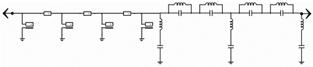
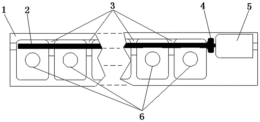
[0028] There are coupling rod 2, polytetrafluoroethylene medium 3, microstrip line 4, LC filter 5, and resonator 6 in the cavity 1. The coupling rod 2 is connected with four parallel resonators 6 to form the first stop band filter. The resonator 6 is a normalized frequency generator, which plays the role of generating frequency signals in the cavity 1, and the coupling rod 2 is three normalized couplers in series, and the coupling rod passes through the microstrip line 4 and the second stopband filter The second stop band filter is composed of three series LC resonators and four parallel LC resonators 5, the coupling rod 2 outputs the frequency signal to the microstrip line 4, and the polytetrafluoroethylene medium 3 fixes the coupling rod, The stopband bandwidth is realized by adjusting the distance between the coupling rod 2 and the resonator 6, the frequency can be adjusted by using the resonator 6, and finally the output of the first stopband filter is transmitted to the se...


PUM


Abstract

The invention provides a multi-frequency multiplication double stop-band filter, solving the problem that the passband bandwidth of a normal stop-band filter is relatively narrow and a multi-frequency multiplication ultra wide band stop-band filter multi frequency multiplication is difficult to realize. The multi-frequency multiplication double stop-band filter is characterized in that a coupling rod (2) is connected with a plurality of parallel resonators (6) to form a first stop-band filter; the resonators (6) are normalized frequency generators, and are used for generating frequency signals in a cavity (1); the coupling rod (2) is a plurality of serial normalized couplers; the coupling rod (2) is connected with a second stop-band filter through a microstrip line (4); the second stop-band filter is formed by a plurality of serial and parallel LC resonators (5); and the output of the first stop-band filter is transmitted to the LC resonators (5) of the second stop-band filter again through the microstrip line (4).

Description

Technical field: [0001] The present invention relates to stopband filters. Background technique: [0002] If a conventional stopband filter needs to have two stopbands in the same passband, two filters are required to achieve it, and it is also easy to appear that the multi-octave harmonics of the first stopband will appear in the other stopband filter In the band, it is difficult to realize the multi-frequency double stop-band filter if the conventional method is used. Some existing conventional filters mainly have the following characteristics: [0003] 1. Some stop-band filters on the market are a single stop-band filter, and there is no characteristic of two stop-band filters in the same passband. [0004] 2. Conventional stop-band filters have a relatively narrow passband bandwidth, and it is difficult to realize multi-multiplier ultra-wideband stop-band filters. Invention content: [0005] The object of the present invention is to provide a multi-octave double stop...

Claims


Application Information

Patent Timeline
Patent Type & Authority Applications(China)
IPC IPC(8): H01P1/203
CPCH01P1/203
Inventor 李承泽
Owner DFINE TECH
Why Eureka
Try Eureka