Microstrip antenna and implantable medical appliance with application of microstrip antenna

A technology of microstrip antennas and antennas, applied in antennas, antenna components, antenna grounding devices, etc., can solve problems such as large thickness and complex structures, and achieve the effects of increased gain, small resonance frequency, and long current path

Inactive Publication Date: 2016-08-03
CHENGDU UNIV OF INFORMATION TECH
View PDF1 Cites 5 Cited by
  • Summary
  • Abstract
  • Description
  • Claims
  • Application Information

AI Technical Summary

Problems solved by technology

However, microstrip implanted antennas using laminated radiators tend to have larger thicknesses and more complex structures although they have smaller planar dimensions
Secondly, the bandwidth of the antenna is about 25MHz, which can easily affect the normal operation of implantable medical devices due to changes in the electrical performance parameters of human tissue

Method used


Image

  • Microstrip antenna and implantable medical appliance with application of microstrip antenna
  • Microstrip antenna and implantable medical appliance with application of microstrip antenna
  • Microstrip antenna and implantable medical appliance with application of microstrip antenna

Examples


Embodiment 1

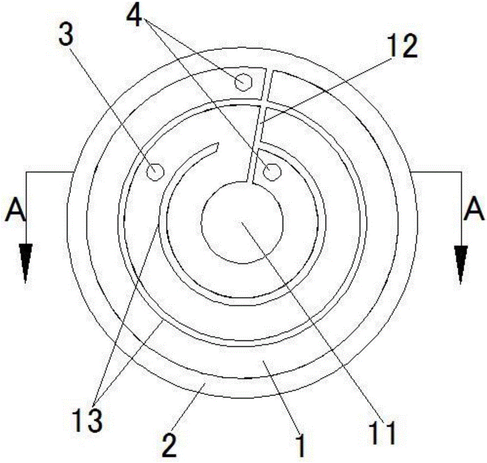
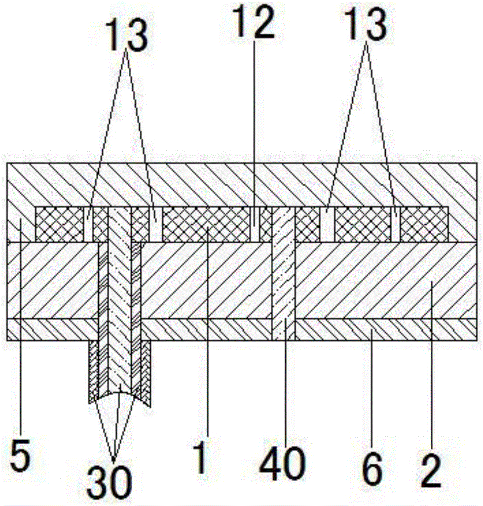
[0024] from figure 1 It can be seen that the outer side of the radiation sheet 1 is an arc line with a radius of 6.6 mm, and the inner side includes a central groove 11 , a rectangular groove 12 and two arcuate grooves 13 . The central groove 11 and the two arc-shaped grooves 13 are concentric with the arc line, and the central groove 11 is a circular groove. The rectangular groove 12 connects the outer circular arc line of the central groove 11 and the radiation sheet 1 and coincides with the radius of the circular arc line; wherein, the beginning and end of the first circular arc groove 13 are connected with the rectangular groove 12, and the second circular arc The beginning of the shaped slot 13 is connected to the rectangular slot 12; the first arc slot 13 (the arc slot near the outer arc line) divides the radiation piece into an inner ring and an outer ring, and the mutual coupling between the inner ring and the outer ring can generate double resonance , thus significan...

Embodiment 2

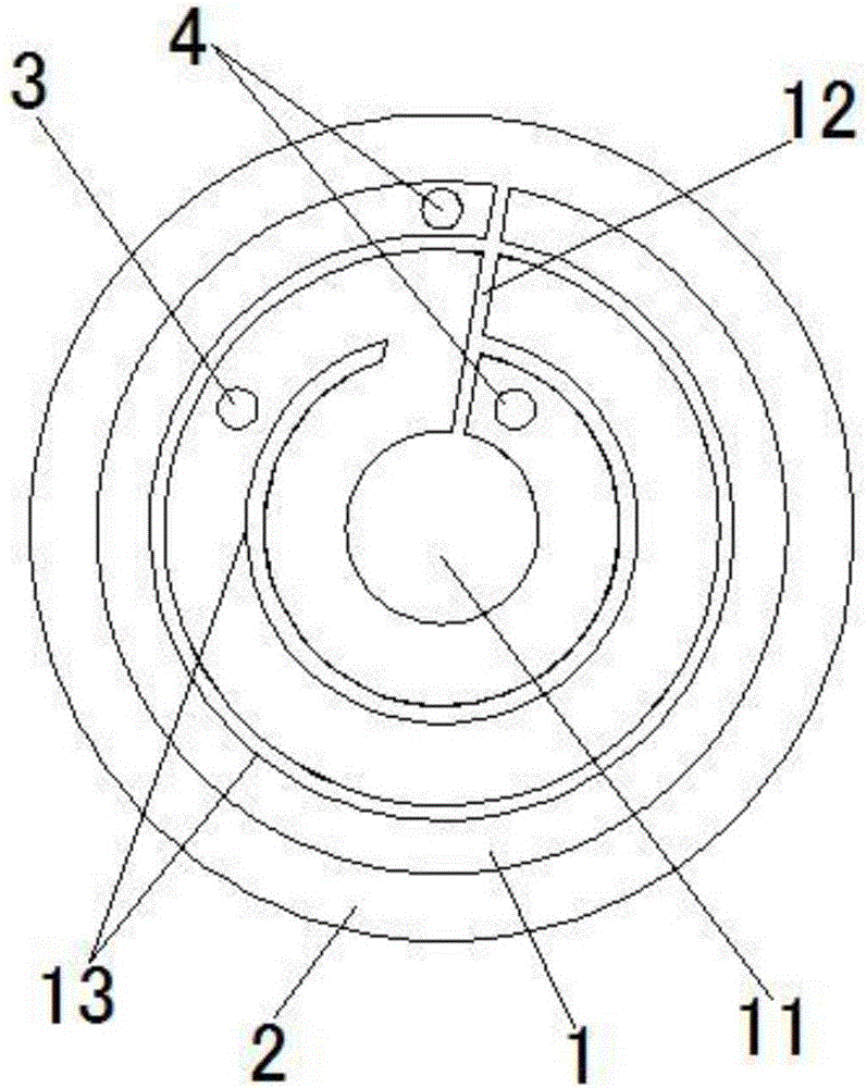
[0028] Such as image 3 As shown, the main difference between the microstrip antenna of this embodiment and the microstrip antenna described in Embodiment 1 is that the width of the arc strips is different, wherein the arc strip width of the inner ring is 1.7mm, and the arc strip width of the outer ring The width of the shaped strip is 1.5mm. For connection methods of central groove 11, rectangular groove 12 and circular arc groove 13, see image 3 . For the corresponding microstrip antenna structure, refer to the pair in Embodiment 1 figure 2 The description of the microstrip antenna has been tested, and the performance of the microstrip antenna is good, so I won't repeat it here.

Embodiment 3

[0030] Such as Figure 4 As mentioned above, the outer side of the radiation sheet 1 is an elliptical arc, and the inner side includes a central groove 11 , a rectangular groove 12 and three elliptical arc grooves 13 . The central groove 11 and the three elliptical arc grooves 13 are coaxial and concentric with the elliptical arc, and the central groove 11 is an elliptical groove. The rectangular groove 12 coincides with the minor axis of the arc of the ellipse. Among them, the beginning and end of the first arc-shaped groove 13 are connected with the rectangular groove 12, the beginning of the second arc-shaped groove 13 is connected with the rectangular groove 12, and the end of the third arc-shaped groove 13 is connected with the rectangular groove; The widths of the three elliptical arc-shaped grooves 13 are all 0.3 mm; the widths of the arc-shaped strips are all 1.7 mm. Compared with Example 1, the radiation sheet of the inner ring has a longer current path. For the co...


PUM


Abstract

The invention discloses a microstrip antenna, wherein the outer side of a radiation plate of the antenna is an arc line, and the inner side comprises a center groove, a rectangular groove and n arc grooves; the rectangular groove is connected to the center groove and the outer side of the radiation plate; the arc grooves are located between the center groove and the outer side arc line; the head end and the tail end of the first arc groove are connected to the rectangular groove, the head end of the second arc groove is connected to the rectangular groove, the tail end of the third arc groove is connected to the rectangular groove, the head end of the fourth arc groove is connected to the rectangular groove, and this rule is obeyed in succession; and n is a natural number which is not smaller than 2. The microstrip antenna has the advantages that a radiation area is large, so gain increase becomes easier; and an arc notching structure is adopted, so that a current route is longer, resonant frequency is lower, and the antenna size can be reduced more easily. The first arc groove divides the radiation plate into an inner ring and an outer ring, and double resonance can be generated through mutual coupling of the inner ring and the outer ring, so that a bandwidth of the microstrip antenna can be increased greatly. A medical appliance which takes the microstrip antenna as an implantation antenna has a wide bandwidth and the small size.

Description

technical field [0001] The invention relates to a microstrip antenna, and also relates to an implanted medical device using the microstrip antenna. Background technique [0002] In the telemedicine system, the collected data is transmitted through the implanted antenna, and the data is received through the external antenna to monitor the health status of the human body. Implantable antennas are therefore key components in telemedicine systems. One of its fields of application is implantable medical devices. Implantable antennas inside the human body face many challenges, such as: miniaturization, energy consumption, biocompatibility, and safety, etc. Among them, the bandwidth determines whether the antenna can work normally due to the influence of frequency offset after the antenna is implanted in the human body or animal tissue, and the miniaturization determines the comfort of the human body or animal after the antenna is implanted in the human body or animal tissue, so ...

Claims


Application Information

Patent Timeline
Patent Type & Authority Applications(China)
IPC IPC(8): H01Q1/38H01Q1/48H01Q1/50H01Q1/27
CPCH01Q1/273H01Q1/38H01Q1/48H01Q1/50
Inventor 李荣强李波杜国宏
Owner CHENGDU UNIV OF INFORMATION TECH
Why Eureka
Try Eureka