Bottom polishing machine for revolving body workpiece

A polishing machine and body workpiece technology, which is applied to surface polishing machine tools, grinding workpiece supports, grinding/polishing equipment, etc., can solve the problems of high labor cost and low efficiency, achieve low labor cost, reduce environmental pollution, The effect of high polishing efficiency

Inactive Publication Date: 2016-08-10
ZHEJIANG KELAODE INTELLIGENT EQUIP CO LTD
View PDF6 Cites 4 Cited by
  • Summary
  • Abstract
  • Description
  • Claims
  • Application Information

AI Technical Summary

Problems solved by technology

The traditional method is to manually polish the surface of the rotating body with p

Method used


Image

  • Bottom polishing machine for revolving body workpiece
  • Bottom polishing machine for revolving body workpiece
  • Bottom polishing machine for revolving body workpiece

Examples


Example Embodiment

[0023] Example 1:

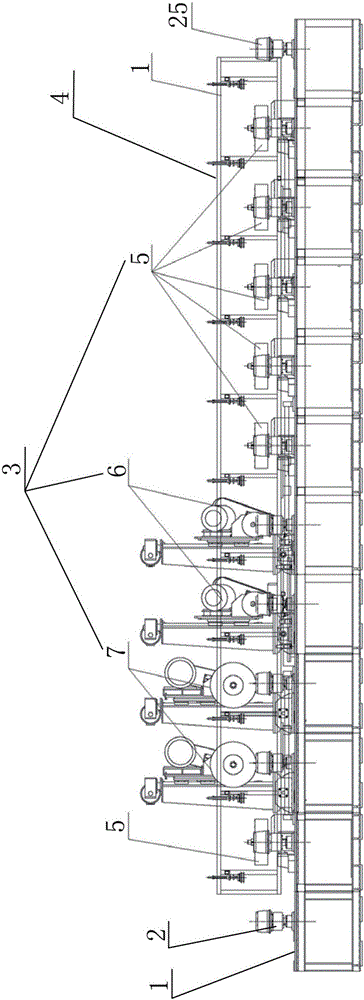
[0024] like Figure 1 to Figure 11 A polishing production line for rotary workpieces shown includes a worktable 1 arranged along the assembly line, on which a plurality of positioning mechanisms 2 for fixing rotary workpieces 25 are evenly spaced. One side of the workbench 1 is provided with a polishing mechanism 3 for polishing the rotary workpiece 25, and the other side of the workbench 1 is provided with a displacement mechanism 4 for shifting the rotary workpiece 25. As the polishing progresses, the shifting mechanism 4 sequentially shifts the rotary workpiece 25 from the positioning mechanism 2 at the beginning of the assembly line to the positioning mechanism 2 at the next stage until the end of the assembly line.

[0025] The positioning mechanism 2 includes a positioning head 16 , a rotating connector 17 , a rotating main shaft 18 and a rotating motor 19 . The upper end of the rotating connector 17 is connected with the positioning head 16, and th...

Example Embodiment

[0033] Example 2:

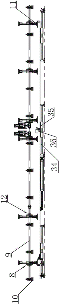
[0034] The difference between this embodiment and Embodiment 1 is that: the lifting cylinder 11 for controlling the lifting of the pneumatic suction cup installation shaft 9 is also arranged in the cutting frame 8 , and the pneumatic suction cup 10 is arranged directly above the positioning mechanism 2 .

Example Embodiment

[0035] Example 3:

[0036] The difference between the present embodiment and the second embodiment is that no pushing mechanism 12 is provided in the cutting frame 8 .


PUM


Abstract

The invention relates to a bottom polishing machine for a revolving body workpiece. The bottom polishing machine comprises a rack, wherein a horizontal adjusting mechanism used for adjusting polishing depth is arranged at the lower end of the rack; a polishing wheel, a polishing machine head and a polishing motor are arranged on the rack; the polishing wheel is in controlled connection with the polishing motor by the polishing machine head; a piece of sanding paper is arranged on the polishing wheel; and a vertical lifting mechanism used for controlling lifting of the polishing machine head and the polishing wheel is arranged on the rack. The bottom polishing machine is high in polishing efficiency and low in labor cost, and can perform line polishing operation on the bottom of a revolving body.

Description

technical field [0001] The invention belongs to the technical field of polishing machines, and in particular relates to a bottom surface polishing machine for a rotary workpiece. Background technique [0002] A body of revolution, assuming two points at both ends of an object, and the two points are connected in a line through the object, and the object takes this line as the center of rotation, and each part of it is the same when it rotates to a fixed position during rotation shape, this is a standard body of revolution. Its characteristic is that the two sides of the center line are symmetrical, so the general rotary body is basically symmetrical. [0003] There are many utensils in life that are rotating bodies, such as the inner pot of the electric rice cooker. When these rotary tools are machined, their surfaces are usually rough and need to be polished. The traditional method is to manually polish the surface of the rotating body with polishing equipment, but this ...

Claims


Application Information

Patent Timeline
IPC IPC(8): B24B29/02B24B27/00B24B55/04B24B55/06B24B41/06B24B41/02B24B41/00B24B47/04
CPCB24B29/02B24B27/0023B24B27/0069B24B27/0076B24B41/005B24B41/02B24B41/06B24B47/04B24B55/04B24B55/06
Inventor 黄建青
Owner ZHEJIANG KELAODE INTELLIGENT EQUIP CO LTD
Why Eureka
Try Eureka