A powder metallurgy brake pad for a train

A powder metallurgy and brake pad technology, applied in friction linings, gear transmission mechanisms, mechanical equipment, etc., can solve the problems of unsmooth wear debris removal channels, affecting braking effect, scratching brake discs, etc. Achieve the effect of preventing the deterioration of the friction state, eliminating abnormal wear and early failure, and preventing eccentric wear

Active Publication Date: 2019-02-01
HUNAN DINGMAO TECH CO LTD
View PDF6 Cites 1 Cited by
  • Summary
  • Abstract
  • Description
  • Claims
  • Application Information

AI Technical Summary

Problems solved by technology

Although the above structure increases the radial gap between the friction blocks, the debris removal channel is not smooth, and there is still a large amount of accumulated debris in the actual use process, scratching the brake disc and affecting the braking effect
[0006] Therefore, how to solve the problem that when the train brakes in rainy snow and high cold environment, it affects normal braking and scratches the brake disc due to accumulation of debris, and develops a kind of vehicle that can be applied to rain snow, high cold environment and normal climate environment. The brake plate structure used then becomes the technical problem that those skilled in the art need to solve

Method used


Image

  • A powder metallurgy brake pad for a train
  • A powder metallurgy brake pad for a train
  • A powder metallurgy brake pad for a train

Examples


Embodiment 1

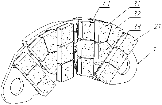
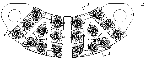
[0055] Referring to the accompanying drawings, this embodiment includes a steel back 1, 2 friction block units I2, 2 friction block units II3 and 2 friction block units III4; the steel back 1 is in a fan-shaped structure; the friction block units I2, friction The block unit II3 and the friction block unit III4 are respectively installed on the steel back 1; the friction block unit I2 is in the shape of a strip; the friction block unit II3 is in the shape of a triangle; the friction block unit III4 is in the shape of a strip The friction block unit II3 is placed between the friction block unit I2 and the friction block unit III4, the friction block unit I2, the friction block unit II3 and the friction block unit III4 are radially arranged along the steel back 1 radial arrangement.

[0056] Between two adjacent friction block units of the friction block unit I2 , the friction block unit II3 and the friction block unit III4 , a chip containing chip discharge groove 5 is formed, a...

Embodiment 2

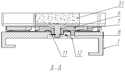
[0065] The difference between this embodiment and Embodiment 1 is that there is one friction block unit I2, one friction block unit II3 and one friction block unit III4; The average width is 40mm. The friction block unit I2 includes 4 friction blocks I21; the friction block unit II3 includes 1 friction block II31, 1 friction block III32 and 1 friction block IV33; the friction block unit III4 includes 4 friction blocks V41 . The radial gap between the friction block I21 and the friction block I21 in the friction block unit I2 is 0.5 mm; the friction block II31 of the friction block unit II3, the friction block III32 and the friction block The radial gap between IV33 is 2 mm; the radial gap between the friction block V41 in the friction block unit III4 and the friction block V41 is 0.5 mm. The friction block I21 is in the shape of a parallelogram; the friction block V41 is in the shape of a parallelogram. The guide post 62 is inserted into the positioning hole 11 of the steel...

Embodiment 3

[0068]The difference between this embodiment and Embodiment 1 is that there are three friction block units I2, three friction block units II3 and three friction block units III4; The average width is 10mm. The friction block unit I2 includes 2 friction blocks I21; the friction block unit II3 includes 1 friction block II31, 1 friction block III32 and 1 friction block IV33; the friction block unit III4 includes 2 friction blocks V41 . The radial gap between the friction block I21 and the friction block I21 in the friction block unit I2 is 2 mm; the friction block II31, the friction block III32 and the friction block IV33 of the friction block unit II3 The radial gap between them is 0.5 mm; the radial gap between the friction block V41 in the friction block unit III4 and the friction block V41 is 2 mm. The friction block I21 is in the shape of a rhombus; the friction block V41 is in the shape of a rhombus. The anti-rotation pin 63 is provided with a pin limiting step 631 , and...


PUM


Abstract

A powder metallurgy brake pad for a train comprises a steel backing, a plurality of friction block units I, a plurality of friction block units II and a plurality of friction block units III; the friction block units I, the friction block units II and the friction block units III are mounted on the steel backing; the friction block units I are in a strip shape; the friction block units II are in a triangular shape; the friction block units III are in a strip shape; the friction block units II are arranged between the friction block units I and the friction block units III; and the friction block units I, the friction block units II and the friction block units III are arranged in a radiation shape in the radial direction of the steel backing. Abrasive dust cannot be stored up in the brake pad, and even if the brake pad is used in the cold environment, the phenomenon that due to ice blocks formed by condensing of the abrasive dust, rain and snow, a brake disc is scratched, and normal braking is affected cannot appear.

Description

technical field [0001] The invention relates to a brake pad for a train, in particular to a powder metallurgy brake pad for a train. Background technique [0002] In the high-speed train disc brake system, the brake pad assembly is a key component. The structure of the brake pad assembly and the connection method between the brake pad and the steel back have a great influence on the performance and cost performance of the brake system. Most of the existing high-speed train brake pads adopt a floating structure. When the train is braking at high speed, the adjustment of the floating structure can ensure the full fit of the friction surface between the friction block and the brake disc and prevent partial wear; but this With this structure, the radial gap between the friction bodies is small, and the debris removal channel is not smooth. During use, especially in rainy, snowy, and high-cold environments, the metal abrasive debris generated by the ice and snow cannot fall off...

Claims


Application Information

Patent Timeline
Patent Type & Authority Patents(China)
IPC IPC(8): F16D69/00F16D69/04
CPCF16D69/00F16D69/04F16D2250/0084
Inventor 蒋建纯肖鹏李细旭崔金罗中保
Owner HUNAN DINGMAO TECH CO LTD
Why Eureka
Try Eureka