Method using anisotropic conductive adhesives to bond display, substrate and external circuit

An anisotropic, external circuit technology, applied in the direction of circuits, conductors, electrical components, etc., can solve the problems of insufficient pressure conductive particles, unbroken pressure, electrode alignment errors, etc., to avoid electrode alignment deviation and low temperature bonding Adverse, reduce adverse effects

Inactive Publication Date: 2016-08-10
BOE TECH GRP CO LTD
View PDF4 Cites 17 Cited by
  • Summary
  • Abstract
  • Description
  • Claims
  • Application Information

AI Technical Summary

Problems solved by technology

[0005] Aiming at the defects of the prior art, the present invention provides an anisotropic conductive adhesive, a display device, a bonding method between the substrate and the external circuit, which can solve the problem of electrode alignment error caused by the external expansion of the external circuit caused by thermal pressure in the prior art, Insufficient pressure makes the conductive particles unbroken or uneven pressure makes some conductive particles not broken, resulting in low conductivity

Method used


Image

  • Method using anisotropic conductive adhesives to bond display, substrate and external circuit
  • Method using anisotropic conductive adhesives to bond display, substrate and external circuit
  • Method using anisotropic conductive adhesives to bond display, substrate and external circuit

Examples


Embodiment Construction

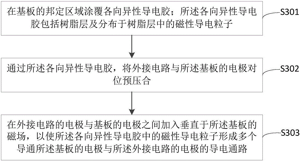
[0035] The following will clearly and completely describe the technical solutions in the embodiments of the present invention with reference to the accompanying drawings in the embodiments of the present invention. Obviously, the described embodiments are only some of the embodiments of the present invention, not all of them. Based on the embodiments of the present invention, all other embodiments obtained by persons of ordinary skill in the art without making creative efforts belong to the protection scope of the present invention.

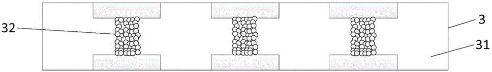
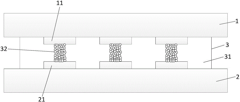
[0036] figure 1 It is a schematic structural diagram of an anisotropic conductive adhesive provided by an embodiment of the present invention, such as figure 1 As shown, the anisotropic conductive adhesive 3 includes: a resin layer 31 and magnetic conductive particles 32 distributed in the resin layer. Wherein, the magnetic conductive particles 32 can be used to form a plurality of aligned conductive paths through the action of a magnetic field,...


PUM


Abstract

The invention provides a method using anisotropic conductive adhesives to bond a display, a substrate and an external circuit. Each anisotropic conductive adhesive comprises a resin layer and magnetic conductive particles that are distributed on the resin layer. The magnetic conductive particles, under the force of a magnetic field, form a plurality of conductive paths in orientation arrangement so that the electrodes at two sides of the anisotropic conductive adhesives are communicated. According to the invention, when anisotropic conductive adhesives are used to bond a substrate and an external circuit, it does not require heating. Therefore, position deviation of electrode pairs driven by the expansion of the external circuit from heated pressure does not occur. At the same time, as the magnetic field induced magnetic conductive particles, short circuits of magnetic conductive particles do not occur as what is seen in the arrangement of other directions. The low conductivity caused by the uneven distribution of traditional conductive particles when they break can also be overcome. With the method, even at a low temperature, a bonding effect can be achieved with high efficiency.

Description

technical field [0001] The invention relates to the field of display technology, in particular to an anisotropic conductive adhesive, a display device, and a bonding method for a substrate and an external circuit. Background technique [0002] With the continuous development of display technology, flat panel displays such as Organic Light Emitting Diode (OLED for short), Plasma Display Panel (PDP for short) and Liquid Crystal Display (LCD for short) develop rapidly. [0003] Existing flat panel displays generally include a display panel and an external circuit, wherein the external circuit transmits driving signals to each signal line in the display panel by being electrically connected to the substrate of the display panel. The electrical connection between the external circuit and the substrate of the display panel is generally realized by crimping with anisotropic conductive film (ACF for short), such as thermal pressing. [0004] In the traditional manufacturing process...

Claims


Application Information

Patent Timeline
Patent Type & Authority Applications(China)
IPC IPC(8): H01B5/16H01L23/488H01L21/603
CPCH01B5/16H01L23/488H01L24/82H01L2224/82203H01L2224/82874
Inventor 李红
Owner BOE TECH GRP CO LTD
Why Eureka
Try Eureka