
Battery module comprising shell, cells, and cooling device, and method for cooling cells of battery

A battery module, battery cell technology, applied in battery/fuel cell control devices, secondary batteries, control devices, etc., can solve problems such as cost increase

Active Publication Date: 2016-08-10
ROBERT BOSCH GMBH
View PDF8 Cites 5 Cited by
  • Summary
  • Abstract
  • Description
  • Claims
  • Application Information

AI Technical Summary

Problems solved by technology

[0007] However, these devices of the prior art have the disadvantage that the cells must be electrically insulated from each other, which leads to increased costs

Method used


Image

  • Battery module comprising shell, cells, and cooling device, and method for cooling cells of battery
  • Battery module comprising shell, cells, and cooling device, and method for cooling cells of battery

Examples


Embodiment Construction

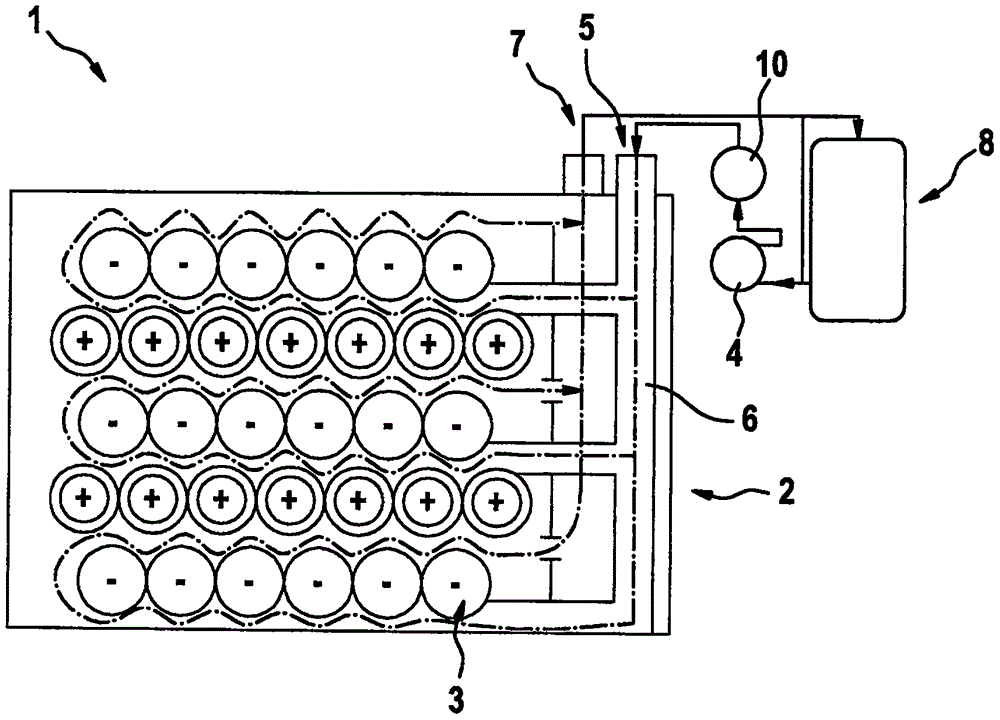
[0025] figure 1 A battery module 1 including a housing 2 is shown. The housing includes a plurality of battery cells 3 . Furthermore, the battery module has at least one inlet or inlet valve 5 for introducing liquid cooling fluid 6 and at least one outlet or outlet valve 7 for discharging cooling fluid 6 . Furthermore, the battery module includes a cooling device 4 , such as a heat exchanger, and / or a circulation device 10 , such as a pump. exist figure 1 , the cooling fluid flows into the battery module via the inlet valve 5 and then flows in countercurrent direction through the channel formed by the individual battery cells. The device also has an external device 8 for cooling the cooling fluid 6 .

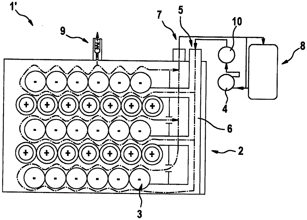
[0026] figure 2 A further battery module 1' is shown. as in figure 1 As in , the liquid cooling fluid flows from the device 8 for cooling the cooling fluid through the inlet valve 5 into the battery module 1 ′ and leaves the battery module 1 ′ through the outlet valve 7 ...


PUM

PropertyMeasurementUnit
Dielectric strengthaaaaaaaaaa

Abstract

The invention relates to a battery module (1;1'), which comprises a shell (2), at least one cell (3) arranged in the shell (2), at least one cooling device (4), at least one inlet (5) for introducing a cooling liquid (6) into the battery, and an outlet for discharging the cooling liquid (6); wherein the cooling liquid (6) is an electrical insulator. The invention also relates to a method.

Description

technical field [0001] The invention relates to a battery module and a method for cooling at least one battery cell arranged in a housing. Background technique [0002] It is foreseeable that not only in stationary applications such as wind turbines but also in mobile applications such as electric vehicles (EV), hybrid electric vehicles (HEV) or plug-in hybrid vehicles ( In plug-in hybrid electric vehicles (PHEV), as a rechargeable electrical energy storage (EES, electro-chemical storage system, ESS), new battery systems or battery modules, such as lithium-ion batteries, will be used more and more ground use. [0003] The battery system comprises a plurality of battery cells, for example cylindrical or prismatic battery cells with electrode coils (cell coils, cell coils, Jerry Roll, JR). The battery cells can be connected in series (serial connection) to increase voltage and / or in parallel to increase maximum current and capacity. As a result, the battery cells can be com...

Claims


Application Information

Patent Timeline
IPC IPC(8): H01M10/613H01M10/0567H01M10/0568H01M10/04H01M10/058
CPCH01M10/04H01M10/0567H01M10/0568H01M10/058H01M10/613B60L2240/545B60L58/26H01M10/6551H01M10/6567Y02E60/10Y02T10/70Y02P70/50
Inventor T·克雷特施马M·格拉奇P·雷曼恩H·蒂特里奇C·贝伦
Owner ROBERT BOSCH GMBH
Learn More