Planar feed source dielectric lens antenna used for unmanned aerial vehicle platform

A dielectric lens antenna and dielectric lens technology are applied in the directions of antennas, antenna arrays, antenna supports/installation devices, etc., which can solve the problems of difficulty in realizing two-dimensional arrays, high gain of anti-collision radar antennas, and high low-profile gain, and achieve work Wide frequency band, overcome atmospheric attenuation, high gain effect

Inactive Publication Date: 2016-08-10
CHINA EAGLE AVIATION TECH
View PDF4 Cites 15 Cited by
  • Summary
  • Abstract
  • Description
  • Claims
  • Application Information

AI Technical Summary

Problems solved by technology

Especially in the UAV anti-collision radar system, the radar antenna is required to be installed on the wing, and the radiation is radiated in the forward direction, that is, the flight direction. The low-profile characteristics of the wing, the end-fire antenna meets such requirements, and the planar asymptotic slot antenna fed by the substrate integrated waveguide is used as an end-fire antenna, which has the characteristics of low profile and high gain, and is easy to integrate with the front end. A planar asymptotic slot antenna is easy to implement a one-dimensional array, but it is difficult to implement a two-dimensional array

Method used


Image

  • Planar feed source dielectric lens antenna used for unmanned aerial vehicle platform
  • Planar feed source dielectric lens antenna used for unmanned aerial vehicle platform
  • Planar feed source dielectric lens antenna used for unmanned aerial vehicle platform

Examples


Embodiment Construction

[0016] The specific embodiments of the present invention are described below so that those skilled in the art can understand the present invention, but it should be clear that the present invention is not limited to the scope of the specific embodiments. For those of ordinary skill in the art, as long as various changes Within the spirit and scope of the present invention defined and determined by the appended claims, these changes are obvious, and all inventions and creations using the concept of the present invention are included in the protection list.

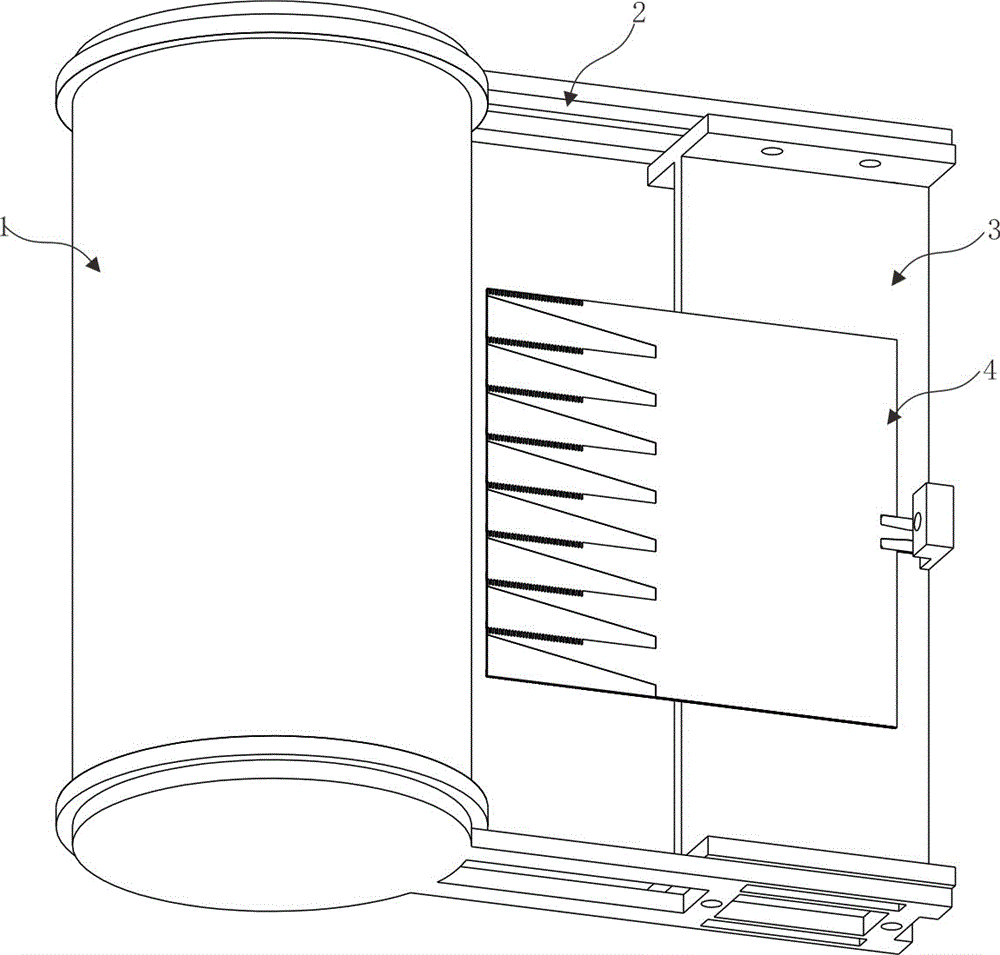
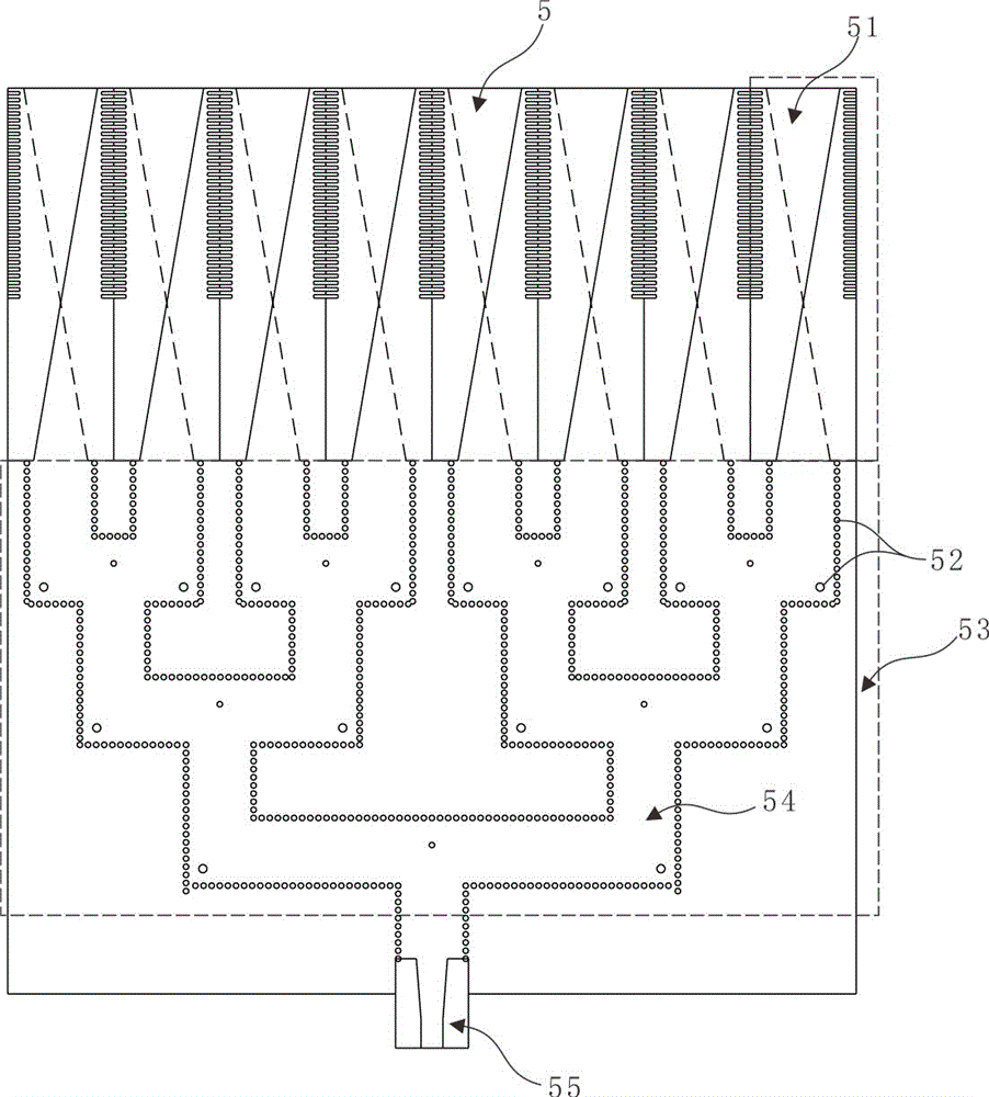
[0017] refer to figure 1 and figure 2 , figure 1 A perspective view showing a planar feed cylindrical dielectric lens 1 antenna for an unmanned aerial vehicle platform; figure 2 A schematic plan view of an array antenna feed 5 printed on a dielectric substrate 4 is shown.

[0018] Such as figure 1 As shown, the planar feed cylindrical dielectric lens 1 antenna for the UAV platform includes a cylindrical dielectric len...


PUM


Abstract

The invention discloses a planar feed source dielectric lens antenna used for an unmanned aerial vehicle (UAV) platform, comprising a cylindrical dielectric lens, a lens mount fixedly clamping the cylindrical dielectric lens, and a feed source mount installed at the free end of the lens mount and used for fixing a dielectric substrate; an array antenna feed source is printed on the dielectric substrate, and is located directly under the cylindrical dielectric lens; a gap exists between the top end of the array antenna feed source and the lower surface of the cylindrical dielectric lens; the array antenna feed source comprises at least one progressive groove antenna unit, a substrate integrated waveguide power dividing feed network in connection with the progressive groove antenna unit, and a microstrip line in connection with the substrate integrated waveguide power dividing feed network; the arrangement direction of the at least one progressive groove antenna unit is consistent with the axial direction of the cylindrical dielectric lens.

Description

technical field [0001] The invention relates to a communication device in an unmanned aerial vehicle, in particular to a planar feed medium lens antenna for an unmanned aerial vehicle platform. Background technique [0002] At present, microwave systems have been developed towards higher frequencies, especially in the field of millimeter waves, the design of the antenna is very important. On high-altitude aircraft platforms, antennas are required to be small in size, light in weight, and conform to the platform. Especially in the UAV anti-collision radar system, the radar antenna is required to be installed on the wing, and the radiation is radiated in the forward direction, that is, the flight direction. The low-profile characteristics of the wing, the end-fire antenna meets such requirements, and the planar asymptotic slot antenna fed by the substrate integrated waveguide is used as an end-fire antenna, which has the characteristics of low profile and high gain, and is ea...

Claims


Application Information

Patent Timeline
Patent Type & Authority Applications(China)
IPC IPC(8): H01Q1/12H01Q1/38H01Q1/50H01Q19/06H01Q21/00
CPCH01Q1/12H01Q1/38H01Q1/50H01Q19/06H01Q21/00
Inventor 邵振海李鹏凯宋鸿
Owner CHINA EAGLE AVIATION TECH
Why Eureka
Try Eureka