Optical fiber detecting device for kilometer-grade measurement distance

A technology for distance measurement and optical fiber detection. It is applied in electromagnetic wave transmission systems, electrical components, transmission systems, etc., and can solve the problems of limited frequency sweep range and microwave drive signal bandwidth.

Inactive Publication Date: 2016-08-10
JIANGSU JUNLONG ELECTRIC TECH
View PDF4 Cites 7 Cited by
  • Summary
  • Abstract
  • Description
  • Claims
  • Application Information

AI Technical Summary

Problems solved by technology

The technical bottleneck faced by this method is that the frequency sweep range is limited by the

Method used


Image

  • Optical fiber detecting device for kilometer-grade measurement distance

Examples


Embodiment Construction

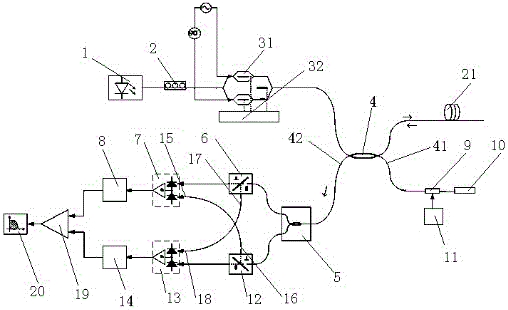
[0014] The optical fiber detection device for kilometer-level distance measurement of the present invention includes a frequency-sweeping laser source 1, a PC module 2 connected to the frequency-sweeping laser source 1, a linear scanning drive control module connected to the PC module 2, and a linear scanning drive control module connected to the linear scanning drive control module. Coupler 4, the optical fiber 21 to be detected connected with the coupler 4, the coupler 4 is provided with a third pin 41 and a fourth pin 42 for coupling, the third pin 41 is connected with the reference signal branch, the fourth The pin 42 is connected with the control circuit module, and the control circuit module includes an encoder 5 connected in series in sequence and a first branch connected to the encoder 5, and the first branch includes a first polarization splitter 6 connected in series, a first balanced receiver 7 and the first square filter 8, and the encoder is connected to the fourth...


PUM


Abstract

The invention discloses an optical fiber detecting device for a kilometer-grade measurement distance, which is characterized in that the optical fiber detecting device comprises a swept laser source, a PC module, a linear scanning driving control module, a coupler and a to-be-detected optical fiber. The coupler is provided with a third pin and a fourth pin for coupling. The third pin is connected with a reference signal branch circuit. The fourth pin is connected with a control circuit module. The control circuit module comprises an encoder and a first branch circuit which is serially connected with the encoder. The first branch circuit comprises a first polarizing beam splitter, a first balancing receiver and a first square filter, wherein the first polarizing beam splitter, the first balancing receiver and the first square filter are serially connected. The encoder is connected with the fourth pin. A closed-loop feedback optical phase locked laser frequency sweeping method is utilized. Laser with a linear frequency sweeping range of 60GHz and line width smaller than 10KHz is realized. The optical fiber detecting device can support an optical frequency domain reflector in the kilometer distance range.

Description

technical field [0001] The invention relates to an optical fiber detection device, in particular to an optical fiber detection device for kilometer-level distance measurement. Background technique [0002] The laser line width and scanning frequency range determine the measurable distance range and positioning accuracy of OFDR respectively. The currently reported laser frequency sweeping can be divided into two categories: first, laser internal modulation frequency sweeping. The laser frequency sweep is realized by tuning the parameters of the laser resonator. The main technical bottleneck faced by this frequency sweep method is that the laser line width and the sweep frequency range are mutually restricted. The narrow linewidth laser has a long resonant cavity or a composite cavity, and the mode selection mechanism is complicated, resulting in a limited scanning range and a centimeter-level positioning accuracy; on the contrary, the linewidth of a short-cavity or single-ca...

Claims


Application Information

Patent Timeline
IPC IPC(8): H04B10/071
CPCH04B10/071
Inventor 朱俊
Owner JIANGSU JUNLONG ELECTRIC TECH
Why Eureka
Try Eureka