Photographing device and electronic device with the photographing device

A shooting device and circuit board technology, which is applied in the electronic field, can solve the problems of limited wiring and layout space of the zoom camera module circuit board, limited heat dissipation design of the zoom camera module area, and the inability to apply ultra-thin mobile phones, etc., to achieve local solution Heat generation problem, saving wiring and layout space, and the effect of large wiring and layout space

Active Publication Date: 2016-08-10
VIVO MOBILE COMM CO LTD
View PDF7 Cites 7 Cited by
  • Summary
  • Abstract
  • Description
  • Claims
  • Application Information

AI Technical Summary

Problems solved by technology

[0004] In the related art, the components of the internal circuit of the zoom camera module (such as the sensor module and the motor drive module) are concentratedly placed on the small circuit board of the zoom camera module, and heat generation is a big problem, especially as the number of pixels of the camera increases. The higher the frame rate, the higher the frame rate, and the higher the optical performance, the more serious the heat, especially some zoom camera modules with PDAF (phase detection auto focus, phase detection autofocus) image sensor modules Due to power consumption and heating problems, it cannot be applied to ultra-thin mobile phones, and the heat dissipation design of the ultra-thin mobile phone in the zoom camera module area is limited. To apply the zoom camera well will face the bottleneck of solving the heat dissipation problem.
In addition, the wiring and layout space inside the zoom camera module circuit board is limited, and the interference of the motor drive module to the sensor module is also a difficult problem in the design of the zoom camera module.
Due to the existence of interference, the motor drive module can only drive the motor in a linear drive mode to reduce interference, but cannot drive the motor in a low-power PWM (Pulse Width Modulation, pulse width modulation) drive mode

Method used


Image

  • Photographing device and electronic device with the photographing device
  • Photographing device and electronic device with the photographing device
  • Photographing device and electronic device with the photographing device

Examples


Embodiment Construction

[0024] In order to make the above objects, features and advantages of the present invention more comprehensible, the present invention will be further described in detail below in conjunction with the accompanying drawings and specific embodiments.

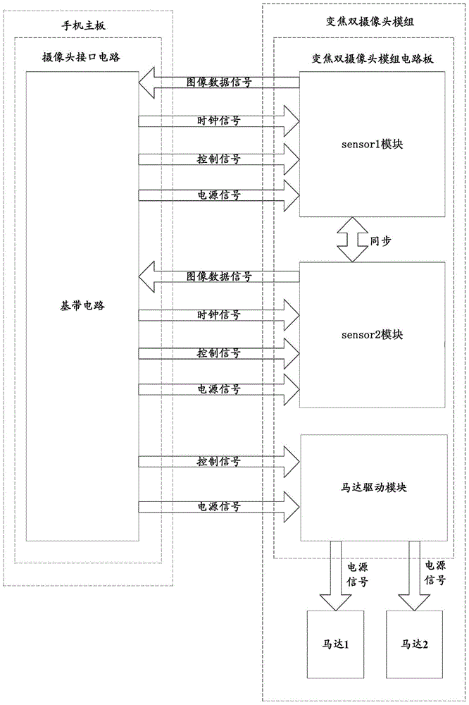
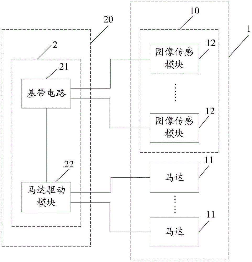
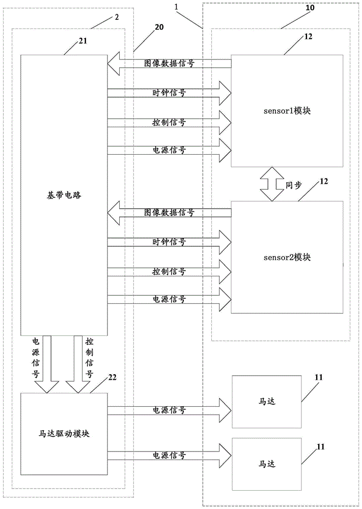
[0025] One of the core ideas of the embodiments of the present invention is that the camera module (such as a zoom dual camera module) does not include a motor driver module, but the motor driver module is arranged on a motherboard with good heat dissipation conditions, so that the related problems can be better solved. In the technology, the local heating problem of the camera module (such as the zoom dual camera module) and the interference problem of the motor drive module in the camera module to the image sensor module can also greatly save the wiring and layout space of the camera module circuit board .

[0026] refer to figure 2 , shows a structural block diagram of an embodiment of a photographing device according to the ...


PUM


Abstract

Embodiments of the present invention provide a photographing device and an electronic device having the same. The photographing device includes: an interface circuit of a camera module, the interface circuit of the camera module is arranged on a main board, and the interface circuit of the camera module includes: a baseband circuit; The motor drive module is connected to the baseband circuit; the camera module includes: a camera module circuit board, and the camera module circuit board includes at least one image sensing module, and each image sensing module is connected to the baseband circuit; at least one motor , each motor is correspondingly connected to the motor drive module. The embodiment of the present invention effectively reduces the problem of local heating of the camera module (such as a zoom dual camera module) in the related art, provides a good user experience, and avoids the interference of the motor drive module to each image sensing module in the camera module. At the same time, it also greatly saves the wiring and layout space of the camera module circuit board.

Description

technical field [0001] The invention relates to the field of electronic technology, in particular to a photographing device and an electronic device. Background technique [0002] At present, camera technology has been widely used in mobile phones. With the rapid development of mobile phones, users' requirements are getting higher and higher. Even better, at the same time, the design of mobile phones has higher and higher requirements for camera modules. For example, the camera module is required not to overheat locally during work, otherwise it may cause the local temperature of the whole machine to be too high and reduce the comfort of user experience. feel. [0003] In the related art, the internal circuit of the zoom camera module mainly includes a sensor module (image sensing module), a motor and a motor driving module. For example, if figure 1 The shown zoom dual camera module includes sensor1 module, sensor2 module, motor driver module, motor1 and motor2. Wherein,...

Claims


Application Information

Patent Timeline
Patent Type & Authority Applications(China)
IPC IPC(8): H04N5/225H04N5/232
Inventor 吕宗安
Owner VIVO MOBILE COMM CO LTD
Why Eureka
Try Eureka