A cam type sprinkler

A sprinkler irrigation and cam-type technology, which is applied in watering devices, gardening, agriculture, etc., can solve the problem of overlapping irrigation surfaces, waste of irrigation dead ends, no significant improvement in the uniformity of sprinkler irrigation, and inability to solve the problem of overlap of sprinkler irrigation surfaces, etc. problems, to achieve the effect of ensuring water source, improving stability, and simple operation

Active Publication Date: 2019-02-05
KUNMING UNIV OF SCI & TECH
View PDF17 Cites 0 Cited by
  • Summary
  • Abstract
  • Description
  • Claims
  • Application Information

AI Technical Summary

Problems solved by technology

[0003] In recent years, a lot of equipment has been developed around water-saving sprinkler irrigation and small and medium-sized sprinkler irrigation machines, such as the authorized invention patent of a spray gun with adjustable elevation angle (201320732877.0), the authorized invention patent of a wind-resistant sprinkler irrigation water-saving nozzle robot (201020582747. X), a public invention patent for establishing a three-dimensional dynamic water distribution model for variable speed nozzles (201510543947.1), light winch type sprinkler irrigation machine (201510537883.4), etc. These devices have a good effect on improving the efficiency of sprinkler irrigation, but these sprinkler irrigation machines Most of the sprinkling irrigation surfaces are circular, and the water volume overlap and leakage are serious. In addition, the sprinkler is greatly affected by the terrain during operation, resulting in no significant improvement in the uniformity of sprinkling irrigation. One of the sprinkling irrigation guns with adjustable elevation angle According to the wind speed when the sprinkler is working, adjusting the pitch angle of the sprinkler head through the height adjustment device improves the adaptability of the sprinkler spray gun to the environment. Although the wind resistance and other performances are improved, it cannot solve the problems of overlapping irrigation surfaces, irrigation dead ends and waste; A wind-resistant sprinkler irrigation water-saving sprinkler robot reduces the impact of wind on the accuracy of sprinkler irrigation by adjusting the angle of the sprinkler head and the water pressure, but the sprinkler head still uses ordinary sprinklers, which are no different from ordinary sprinklers in the absence of wind, so there are also some shortcomings of traditional sprinklers; A method for establishing a three-dimensional dynamic water distribution model of variable speed nozzles. By studying the characteristics of various nozzles and adjusting the types of nozzles and the distance between nozzles to improve uniformity, this method is time-consuming and laborious to improve uniformity. The problem of surface overlap is not conducive to water saving; the light winch sprinkler uses the most commonly used wheeled trolley as the carrier, which has high requirements on the terrain and is not conducive to walking on rough roads, and the scope of application is relatively small

Method used


Image

  • A cam type sprinkler
  • A cam type sprinkler
  • A cam type sprinkler

Examples


Embodiment 1

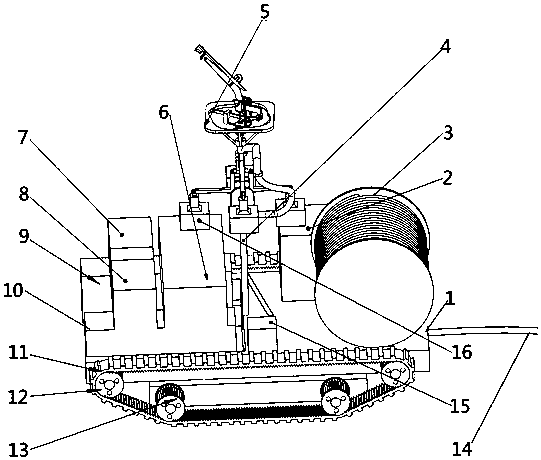
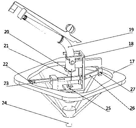
[0039] Embodiment 1: as Figure 1-10 As shown, the cam type sprinkler includes frame 1, water pump assembly 2, reel assembly 3, hard water pipe I4, cam sprinkler head 5, battery 6, drive motor I7, drive motor II8, gearbox I9, gearbox II10 , crawler belt 11, driving track wheel 12, driven track wheel 13, reel water pipe 14, balance device 16; the two crawler belts 11 are respectively installed on both sides of frame 1 by driving track wheel 12 and driven track wheel 13, The active track wheels 12 on both sides of the frame 1 are respectively connected with the gearbox I9 and the gearbox II10 located at the front end of the frame 1, and the drive motor I7 and the drive motor II8 are arranged above the gearbox I9 and the gearbox II10 and connected with the gearbox I9, The gearbox II10 is connected, the water pump assembly 2 is installed at the rear end of the frame 1, the battery 6 is installed on the frame 1 and is located behind the drive motor I7 and the drive motor II8, and t...

Embodiment 2

[0048] Embodiment 2: The structure of the device in this embodiment is the same as in Embodiment 1, the difference is that the device also includes a conventional wireless signal receiving control device 15, and the wireless signal receiving control device 15 is installed in the middle of the frame 1 and is respectively connected to the drive motor I7, drive motor II8, The water pump assembly 2 and the reduction motor 33 are connected to receive remote control signals and control the operation of each motor through conventional techniques.

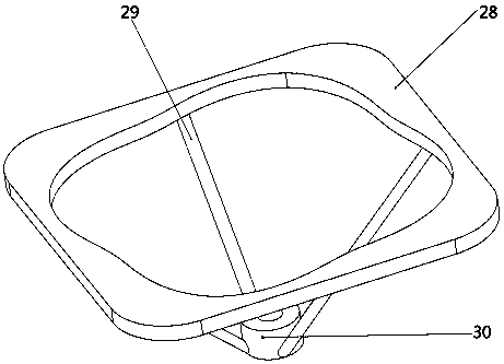
[0049] In the prior art, most of the ordinary nozzles with a circular sprinkling area will have dead ends when sprinkling square cultivated land, and the waste and overlapping parts are unavoidable. This will not occur when using a cam-type sprinkler with a square sprinkling surface to irrigate square cultivated land. Overlap and dead angle are beneficial to water saving and irrigation uniformity.


PUM


Abstract

The invention discloses a cam type jet-irrigating machine and belongs to the technical field of agricultural water-saving irrigation. The cam type jet-irrigating machine comprises a rack, a water pump assembly, a reel assembly, a hard water pipe I, a cam spray head, a storage battery, a drive motor I, a drive motor II, a speed changing box I, a speed changing box II, caterpillar bands, drive crawler wheels, driven crawler wheels, a reel water pipe and a balance device. By means of the cam type spray head which is specially designed, the original circular jet-irrigating area can be converted into a square jet-irrigating area, overlapping of jet-irrigating areas is avoided, jet-irrigating dead corners of a square land can be eliminated, water can be saved, and the jet-irrigating uniformity can be improved. The automatic balance device can solve the problem that in rugged terrain, the shape of the jet-irrigating face changes. A crawler type vehicle serves as a carrier of the jet-irrigating machine, and the jet-irrigating machine can adapt to various complex terrains; the two drive motors serve as a walking power device, the jet-irrigating machine can be more easily and effectively controlled to swerve, automation can be achieved better through motor drive, and the labor intensity of workers can be lowered.

Description

technical field [0001] The invention relates to a cam-type sprinkler irrigation machine, in particular to a cam-type sprinkler irrigation machine with a square irrigation surface, belonging to the technical field of agricultural water-saving irrigation. Background technique [0002] Sprinkler irrigation is an irrigation method that uses special equipment such as sprinklers to spray pressurized water into the air, forming water droplets that fall to the ground sprinkler surface and crop surface. This irrigation method has the advantages of water saving, labor saving, and strong terrain adaptability. Compared with drip irrigation, due to the higher working pressure, it has a faster flow rate and a larger outflow, which reduces the possibility of clogging. A single nozzle can spray a larger area, so the material used per mu is less than that of drip irrigation, saving costs. Therefore, it has broad application prospects. [0003] In recent years, a lot of equipment has been d...

Claims


Application Information

Patent Timeline
Patent Type & Authority Patents(China)
IPC IPC(8): A01G25/09A01G25/16
CPCA01G25/09A01G25/16Y02A40/22
Inventor 杨启良邢浩男贾维兵
Owner KUNMING UNIV OF SCI & TECH
Why Eureka
Try Eureka