Deep dedusting and defogging device

A defogging device, deep technology, applied to the separation of dispersed particles, chemical instruments and methods, separation methods, etc., can solve the problems of disorderly flow of liquid and dust, difficult to meet actual requirements, and unfavorable for droplet settlement, so as to avoid The effects of secondary carrying, improved demisting efficiency, and increased contact area

Active Publication Date: 2016-08-17
TIANJIN XIANGYUANXI ENVIRONMENTAL PROTECTION EQUIP CO LTD +1
View PDF5 Cites 14 Cited by
  • Summary
  • Abstract
  • Description
  • Claims
  • Application Information

AI Technical Summary

Problems solved by technology

In addition, the invention does not have a special drainage channel, and the collected liquid and dust flow in an orderly manner, which is easy to form secondary carryover.
Also, the invention does not have a volume expansion chamber, and the flue gas does not have a deceleration process, which is not conducive to the settlement of droplets
Therefore, its defogging effect is limited, and it is difficult to meet the actual requirements

Method used


Image

  • Deep dedusting and defogging device
  • Deep dedusting and defogging device
  • Deep dedusting and defogging device

Examples


Embodiment 1

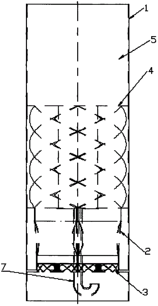
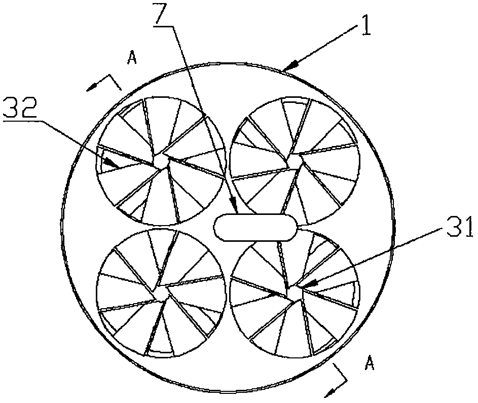
[0040] to combine figure 2 and image 3As shown, the helical channel 4 is a cylindrical helix, and the number of helical turns is not less than half a circle. The cylindrical helix is ​​the helix of the helical channel 4. The front projection of the helix is ​​a sinusoidal curve, and the horizontal projection is a circle. Since the spiral channel 4 is close to the inner wall of the guide tube 1, the gas flowing out from the spiral channel 4 will rise along its tangent, and will be concentrated around the inner wall of the guide tube 1 under the action of the inner wall of the guide tube 1, forming Correspondingly, there is less smoke in the center of the guide tube 1, and most of the smoke continuously collides with the inner wall of the guide tube 1 in the ring-shaped air flow zone, and the smoke flows in a spiral manner. Ascent, the process is longer, so that the fog droplets have sufficient coagulation time, and the demisting effect is improved.

[0041] The center of th...

Embodiment 2

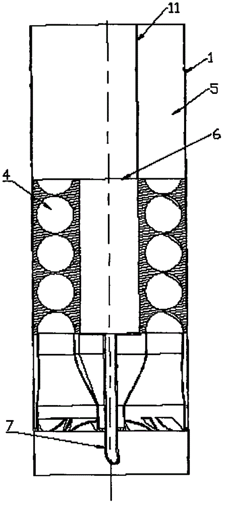
[0051] The difference between this embodiment and Embodiment 1 is that the spiral channel 4 is formed by a plurality of circular tubes spirally along the axial direction of the guide tube 1, the lower end of the circular tube is bent downward to connect with the air flow channel 2, and the upper end is connected to the cavity 5 connected, and the end port is a horizontal cut. Forming the spiral channel 4 in a circular pipe spiral can reduce the amount of processing and reduce the processing cost.

[0052] The guide tube 1 is cylindrical, the spiral channel 4 is installed in the guide tube 1, and its outer wall is attached to the inner wall of the guide tube 1, that is, the outer diameter of the spiral channel 4 is slightly smaller than the inner diameter of the guide tube 1 , the upper and lower ends of the spiral channel 4 are respectively provided with end plates 9, the end plates 9 are used to prevent mist or water droplets from entering the gap between the spiral channel 4...

Embodiment 3

[0054] The difference between the present embodiment and the first embodiment is that the structure of the spiral channel 4 is different. The guide tube 1 of the present embodiment is cylindrical, and a support tube 62 is arranged in the center thereof, and the diameter of the support tube 62 is smaller than that of the guide tube. The inner diameter of the tube 1 is welded with a spiral plate 41 surrounding the support tube 62. The spiral plate 41 is located in the annular area between the guide tube 1 and the support tube 62, and connects the guide tube 1 and the support tube 62. The annular area between them is divided into several separate passages. The spiral plate 41 spirally rises around the support tube 62, its inner side is connected with the outer wall of the support tube 62, and its outer side is connected with the inner wall of the guide tube 1. The adjacent two spiral plates 41 and the outer wall of the support tube 62 and the inner wall of the guide tube 1 jointly...


PUM


Abstract

The invention relates to a deep dedusting and defogging device which comprises flow guide cylinders arranged in an absorption tower, wherein airflow passages are formed in the flow guide cylinders; spiral passages communicated with the airflow passages are further formed above the air flow passages; outlets of the spiral passages are inclined; the cylinder walls of the flow guide cylinders are higher than the outlets of the spiral passages, and volume-enlarged chambers with openings are formed in the position above the spiral passages. According to the device, the spiral passages are additionally formed in the position above the airflow passages, and in a rising process of flue gas, the effect of absorbing dust and removing liquid drops is achieved by virtue of continuous rotation and collision movement between water drops in the flue gas, the water drops and the dust as well as the water drops and the walls of the passage walls under double actions of centrifugal force and inertial collision, so that defogging and dedusting efficiency is effectively improved; in the volume-enlarged chamber, the speed of the flue gas is reduced, the separated liquid drops fall, and the liquid drops are discharged through the downward passages separated from the flue gas, so that secondary carrying is prevented.

Description

technical field [0001] The invention relates to a flue gas treatment device, in particular to a deep dust and mist removal device. Background technique [0002] The mist eliminator is widely used in the liquid droplets entrained by the gas in the separation tower, which can effectively remove the mist droplets and prevent them from being discharged into the atmosphere. The existing mist eliminators mostly adopt the blade type arranged in an array. When , the two-dimensional deflection is realized, and it collides with the blade of the mist eliminator to realize the separation of mist and gas. However, since the mist eliminator with this structure can only realize the two-dimensional rotation of the flue gas, the efficiency of dust removal and mist removal is not high. The Chinese Utility Model Patent No. 201420674592.0 discloses a deep dedusting and demisting device, which is installed in the desulfurization absorption tower on the bottom-up flow section of the saturated fl...

Claims


Application Information

Patent Timeline
Patent Type & Authority Applications(China)
IPC IPC(8): B01D45/08B01D45/16
CPCB01D45/08B01D45/16
Inventor 杨青龙黄敏
Owner TIANJIN XIANGYUANXI ENVIRONMENTAL PROTECTION EQUIP CO LTD
Why Eureka
Try Eureka