
Four-rotor multipurpose flying robot

A technology for flying robots and rotorcraft, applied in the field of robotics, can solve the problems of large influence of land robots, limited working range of robots, and difficulty in improving work efficiency, so as to reduce the probability of accidents, improve maneuverability, and improve efficiency. Effect

Active Publication Date: 2016-08-17
南京航天国器智能装备有限公司 +1
View PDF6 Cites 18 Cited by
  • Summary
  • Abstract
  • Description
  • Claims
  • Application Information

AI Technical Summary

Problems solved by technology

[0002] At present, most of the existing robots are single-function robots designed to solve some specific problems in life and production; however, in real life, we often need robots that can perform multiple tasks, such as scientific investigation, accident rescue, For tasks such as logistics transportation, public security supervision, and garbage cleaning, traditional land robots are greatly affected by terrain factors. In the process of carrying out actual tasks, not only is it difficult to improve work efficiency, but also many places cannot be reached by robots, which limits the work of robots. scope

Method used


Image

  • Four-rotor multipurpose flying robot
  • Four-rotor multipurpose flying robot
  • Four-rotor multipurpose flying robot

Examples


Embodiment Construction

[0020] The present invention will be further described below in conjunction with specific embodiments.

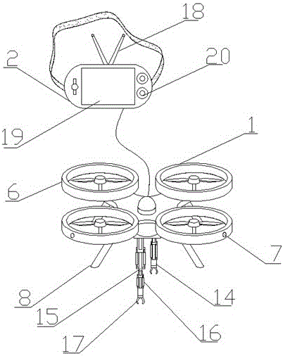
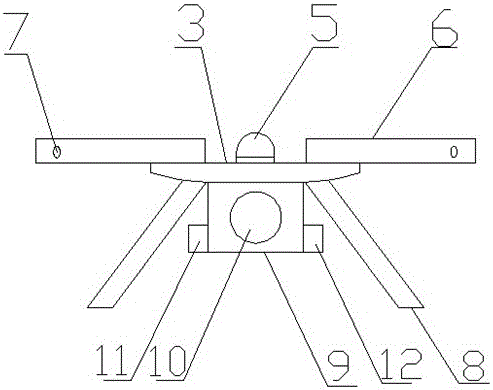
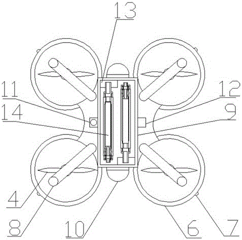
[0021] refer to Figure 1-3 , a four-rotor multi-purpose flying robot, including a rotorcraft 1 and a control device 2, the rotorcraft 1 includes a chassis 3, a propeller 4, a wireless signal transceiver 5, a driving device, a controller and an electric energy storage device, and the chassis 3 is a hollow structure , and the driving device, controller and electric energy storage device are installed inside the chassis 3, the propeller 4 is connected to the driving device through the transmission mechanism, the driving device and the wireless signal transceiver 5 are electrically connected to the controller, and the controller and the electric energy The storage device is electrically connected. The outer side of the propeller of the rotorcraft 1 is provided with an anti-collision ring 6. The outer side of the anti-collision ring 6 is wrapped with an elastic rubber sleeve, a...


PUM


Abstract

The invention relates to a four-rotor multipurpose flying robot which comprises rotorcrafts and a control device, wherein each rotorcraft comprises a base plate, propellers, a wireless signal transceiver, a driving device, a controller and an electric energy storage device; the propellers are in transmission connection with the driving devices through transmission mechanisms; the driving devices and the wireless signal transceivers are electrically connected with the controllers; the controllers are electrically connected with the electric energy storage devices; an anti-collision ring is arranged on the outer side of the propellers of each rotorcraft; the anti-collision rings are fixedly connected to the upper sides of the four corners of the corresponding base plate; an ultrasonic sensor is arranged on the outer wall of one side, away from each base plate, of the corresponding anti-collision ring; the ultrasonic sensors are electrically connected with the controllers; support legs are fixedly arranged on the lower sides of the four corners of each base plate. According to the four-rotor multipurpose flying robot, the ultrasonic sensors are arranged on conventional rotorcrafts, so that the probability of collision of the flying robot in a flying process is reduced, the controllability of the flying robot s improved, meanwhile, flying of the flying robot in a narrow passage is facilitated, and task performance efficiency is improved.

Description

technical field [0001] The invention relates to the technical field of robots, in particular to a four-rotor multipurpose flying robot. Background technique [0002] At present, most of the existing robots are single-function robots designed to solve some specific problems in life and production; however, in real life, we often need robots that can perform multiple tasks, such as scientific investigation, accident rescue, For tasks such as logistics transportation, public security supervision, and garbage cleaning, traditional land robots are greatly affected by terrain factors. In the process of carrying out actual tasks, not only is it difficult to improve work efficiency, but also many places cannot be reached by robots, which limits the work of robots. scope. [0003] To this end, we propose a quadrotor multipurpose flying robot to solve the above problems. Contents of the invention [0004] The purpose of the invention is to solve the background technology and propo...

Claims


Application Information

Patent Timeline
Patent Type & Authority Applications(China)
IPC IPC(8): B64C27/08B64C27/20B64D47/08B64D47/00G05D1/08B25J15/08
CPCG05D1/0808B64C27/08B64C27/20B64D47/00B64D47/08B25J15/08B64U2101/30B64U10/10
Inventor 林建铃林建宝张秀平
Owner 南京航天国器智能装备有限公司
Learn More