Eureka AIR delivers breakthrough ideas for toughest innovation challenges, trusted by R&D personnel around the world.

A method to improve the uniformity of laser far-field spot based on optical ladder

A uniformity and optical ladder technology, used in lidar, laser lighting imaging, laser far-field applications, and optical communication fields, can solve the problem of uneven intensity of far-field spots, overcome unevenness of far-field spots and improve uniformity , the effect of simple structure

Active Publication Date: 2018-04-24
INST OF APPLIED PHYSICS & COMPUTATIONAL MATHEMATICS
View PDF7 Cites 0 Cited by
  • Summary
  • Abstract
  • Description
  • Claims
  • Application Information

AI Technical Summary

Problems solved by technology

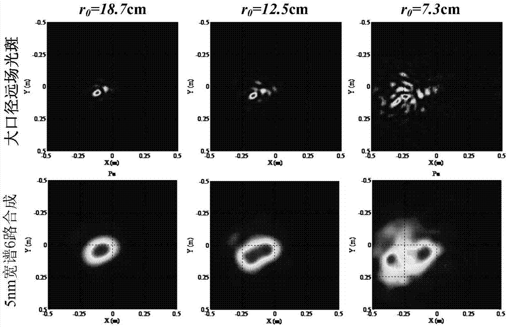
[0005] In order to solve the problem of uneven far-field spot intensity after the laser is transmitted through the turbulent atmosphere, the present invention proposes a method for improving the uniformity of the laser far-field spot based on an optical ladder: use an optical ladder to divide the laser with a certain line width into multiple beams , the optical ladder has multiple sub-apertures, so that the difference between the shortest wavelength beam phase difference and the longest wavelength beam phase difference between the sub-apertures is greater than or equal to 2π; the beams are transmitted through the atmospheric path after being emitted by the emission system, and the same wavelength beams between the sub-apertures are in the target The coherent superposition of different wavelength beams at the target position complements each other in strength and non-coherent superposition to achieve the purpose of improving the uniformity of the laser far-field spot

Method used


Image

  • A method to improve the uniformity of laser far-field spot based on optical ladder
  • A method to improve the uniformity of laser far-field spot based on optical ladder
  • A method to improve the uniformity of laser far-field spot based on optical ladder

Examples


Embodiment Construction

[0023] The present invention will be further described below in conjunction with the examples, but the present invention is not limited to the following examples.

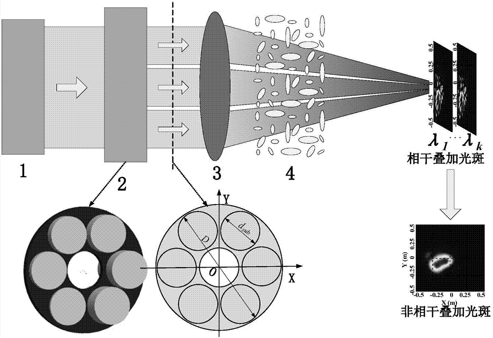
[0024] Such as figure 1 shown, yes figure 1 To illustrate, in the method for improving the uniformity of laser far-field spot based on the optical ladder provided by the present invention, the laser beam output by the laser 1 with a certain line width is incident on the optical ladder 2, and the beam is emitted through the emission system 3 and then passes through the atmospheric path 4 Transmission, to obtain a far-field spot at the target.

[0025] The laser 1 with a certain linewidth is a pulsed laser, and the laser center wavelength λ 0 =1064nm, spectral width Δλ=5nm.

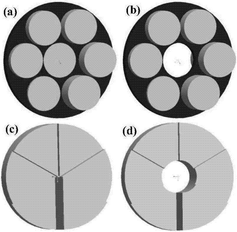
[0026] The optical ladder 2 is transmissive, with 6 sub-apertures arranged in a regular hexagon, and the refractive index of the optical ladder 2 is n 2 =1.5 and the thickness difference between the mth and nth sub-apertures is Such as fi...


PUM


Abstract

The invention relates to a method of increasing laser far-field light spot uniformity based on a light ladder. The method comprises the following steps that the light ladder is used to divide a laser with a certain wire width into multiple beams, the light ladder possesses a plurality of subapertures and a difference of a shortest wavelength light beam phase difference and a longest wavelength light beam phase difference among the subapertures is greater than or equal to 2 pi; the light beams are emitted through an emission system and then are transmitted via an atmosphere path, the light beams with a same wavelength among the subapertures carry out coherence superposition at a target position, coherence superposition light spot intensities of the light beams with different wavelengths at the target position are complementary and incoherent superposition is performed. Therefore, purposes of restraining a turbulence scintillation phenomenon and increasing laser far field light spot uniformity are realized. In the invention, a disadvantage that a single laser far field light spot is nonuniform is overcome; simultaneously, the structure is simple and disadvantages that the structure is complex, and servo control and a coaxial situation are difficult in a traditional multi-beam system are overcome. The method can be used in the fields of laser illumination imaging, optical communication, a laser radar and the like.

Description

technical field [0001] The invention relates to a method for improving the uniformity of laser far-field spots based on an optical ladder, which belongs to the field of laser far-field applications, and also belongs to the fields of laser lighting imaging, optical communication, and laser radar. Background technique [0002] In laser far-field applications, the uniformity of far-field spot intensity distribution is very important. In the laser radar system, the uniformity of light spot intensity distribution is of great significance to the detection and identification of small and dark targets; in the optical communication system, the light intensity distribution in the far field is uniform and stable, which can greatly reduce the bit error rate; In the active illumination imaging system, the illumination laser uniformly illuminates the target area, which can improve the brightness of the target backlight and the clarity of the system imaging, so that the system can accurate...

Claims


Application Information

Patent Timeline
Patent Type & Authority Patents(China)
IPC IPC(8): G02B27/48
CPCG02B27/48
Inventor 罗文张飞舟张建柱安建祝谢晓钢
Owner INST OF APPLIED PHYSICS & COMPUTATIONAL MATHEMATICS
Why Eureka
Eureka Blog
Learn More