

Finite time passive control method for Buck converter
A limited time, passive control technology, applied in control/regulation systems, DC power input conversion to DC power output, instruments, etc., can solve problems such as slow response speed
- Summary
- Abstract
- Description
- Claims
- Application Information
AI Technical Summary
Problems solved by technology
Method used
Image

Examples
Embodiment Construction
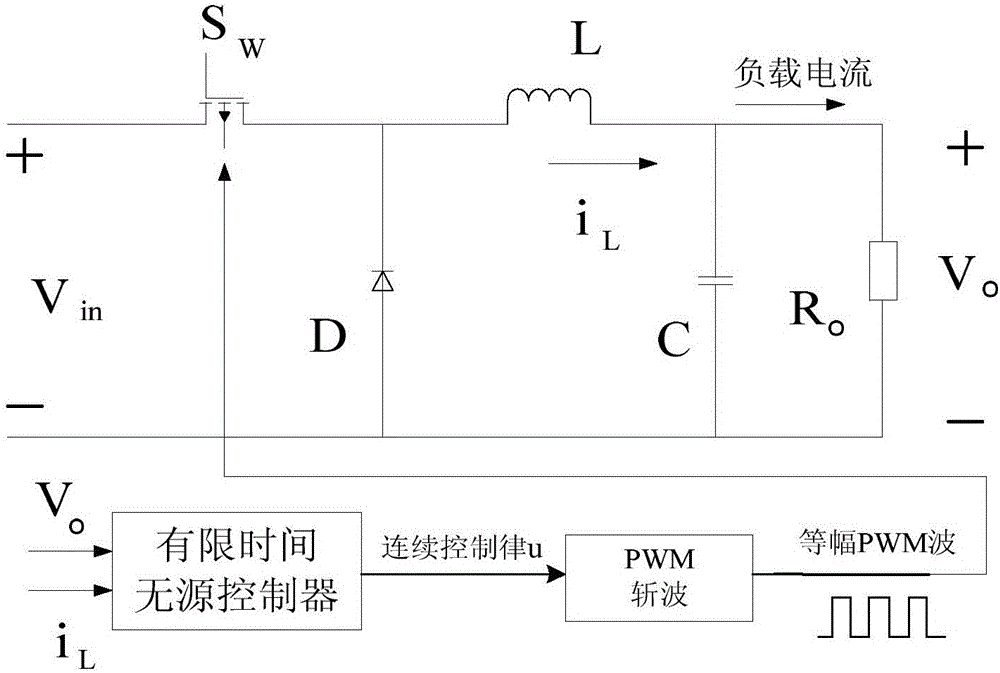
[0032] In order to effectively improve the quality of the output voltage of the Buck converter, stabilize the output voltage within a limited time, and improve the response speed of the output voltage, the technical solution of the present invention is as follows:
[0033] Such as figure 1 The finite-time passive control structure diagram of the Buck converter is shown, and the Buck converter circuit includes a DC voltage source V in , a controllable switch tube S W , a freewheeling diode D, an inductor L, a capacitor C and a load resistor R 0 . Put the DC voltage source V in As a discharge element connected to the input of the Buck converter, the DC voltage source V in The positive pole passes through the controllable switch tube S W And the reverse freewheeling diode D is connected to the DC voltage source V in The negative pole, the inductance L and the capacitance C are connected in series and at both ends of the reverse freewheeling diode D, and the load resistance ...
PUM
 Abstract
Description
Claims
Application Information