Lathe used for turning long rod class of parts

A technology of lathes and long rods, which is applied in the field of lathes for turning long rod parts, and can solve problems such as the clamping arm cannot clamp the workpiece, the stability is reduced, and the length-to-diameter ratio is large.

Inactive Publication Date: 2016-08-24
HUANGHE S & T COLLEGE
View PDF8 Cites 12 Cited by
  • Summary
  • Abstract
  • Description
  • Claims
  • Application Information

AI Technical Summary

Problems solved by technology

[0002] Lathe is the main equipment for mechanical processing. It mainly processes the surface of shaft parts and rotary processing methods such as drilling. Lathe processing has two processing forms: one is to fix the turning tool and process the formed workpiece during rotation; The first is to fix the workpiece, through the high-speed rotation of the turning tool, and the horizontal and vertical movement of the turning tool for precision machining. The lathe is mainly used for machining shafts, discs, sleeves and other workpieces with rotating surfaces. It is used in machinery manufacturing and repair factories. The widest type of machine tool processing; but when the lathe processes the deep hole inner circle of the workpiece, due to the small diameter of the workpiece and the large aspect ratio, the conventional tools on the lathe cannot realize deep hole processing; due to the depth of the hole, the processed tools are all If it is too long, the vibration of the tool cannot be avoided during the processing, and the stability of the processing will be reduced, which will cause damage to the workpiece, and the workpiece can only be replaced, which increases the operating cost;
[0003] In addition, the center frame currently used for machining long shafts on ordinary lathes and small CNC lathes uses a cast iron center frame to clamp the workpiece at three points. It needs to be manually adjusted at any time during...

Method used


Image

  • Lathe used for turning long rod class of parts
  • Lathe used for turning long rod class of parts
  • Lathe used for turning long rod class of parts

Examples


Embodiment Construction

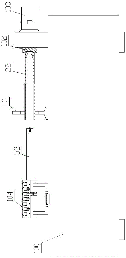
[0023] Such as figure 1 As shown, the lathe for turning long rod parts of the present invention includes a bed 100, a tool bar 52, a tool bar clamping device 104, a jaw type lathe center clamp 101, a chuck 102 and a motor 103, and the motor 103. The center clamper 101 and the tool bar clamping device 104 of the jaw type lathe are fixed on the bed 100, and the main shaft of the motor 103 is fixedly connected with the chuck 102;

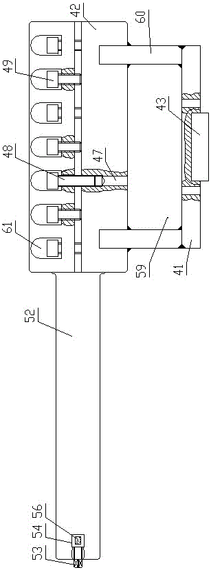
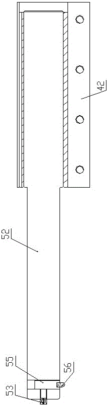
[0024] Such as Figure 2-4 As shown, the tool bar clamping device 104 includes a horizontally arranged base 41 and a tool bar cover 42. The bottom of the base 41 is embedded with a positioning block 43 protruding downward from the lower surface of the base 41. The knife rod cover 42 is fixedly connected, the knife rod cover 42 is a cylindrical structure, the center line of the knife rod cover 42 is horizontally arranged along the left and right directions, and the tool rod cover 42 is provided with a cylindrical mounting cavity 44 along the axial dire...


PUM


Abstract

A lathe used for turning long rod class of parts comprises a lathe body, a cutter bar, a cutter bar clamping device, a clamping jaw type lathe center clamping device, a chuck and a motor, wherein the motor, the clamping jaw type lathe center clamping device and the cutter bar clamping device are fixed to the lathe body, and a main shaft of the motor is fixedly connected with the chuck; and the cutter bar clamping device comprises a horizontally arranged base, a cutter bar and a cutter bar sleeve, a positioning block protruding downwards out of the lower surface of the base is embedded in the bottom of the base, the base is fixedly connected with the cutter bar sleeve through a support base, the cutter bar sleeve is of a cylindrical structure, the central line of the cutter bar sleeve is horizontally arranged in the left and right direction, and a cylindrical mounting cavity is arranged in the cutter bar sleeve in the axial direction. The device is high in processing and turning precision, great in stability, low in defective rate and accurate in centering.

Description

technical field [0001] The invention belongs to the technical field of mechanical processing equipment, and in particular relates to a lathe used for turning long rod parts. Background technique [0002] Lathe is the main equipment for mechanical processing. It mainly processes the surface of shaft parts and rotary processing methods such as drilling. Lathe processing has two processing forms: one is to fix the turning tool and process the formed workpiece during rotation; The first is to fix the workpiece, through the high-speed rotation of the turning tool, and the horizontal and vertical movement of the turning tool for precision machining. The lathe is mainly used for machining shafts, discs, sleeves and other workpieces with rotating surfaces. It is used in machinery manufacturing and repair factories. The widest type of machine tool processing; but when the lathe processes the deep hole inner circle of the workpiece, due to the small diameter of the workpiece and the l...

Claims


Application Information

Patent Timeline
IPC IPC(8): B23B5/08B23B27/16B23B29/04B23Q3/06
CPCB23B5/08B23B27/1662B23B29/04B23Q3/064
Inventor 王瑞利张发厅高德峰董彬史辉孙晨磊崔文豪
Owner HUANGHE S & T COLLEGE
Why Eureka
Try Eureka