Supercharge Your Innovation With Domain-Expert AI Agents!

Multifunctional pipe cutter capable of avoiding scratch

A pipe cutting machine, multi-functional technology, applied in the direction of metal processing machinery parts, clamping, support, etc., can solve the problems of uneven feeding, large vibration and noise, and easy damage of tools, so as to save labor and cost, and position High precision and good stability

Active Publication Date: 2016-08-24
YANCHENG SHUANGJIA ELECTRIC
View PDF6 Cites 3 Cited by
  • Summary
  • Abstract
  • Description
  • Claims
  • Application Information

AI Technical Summary

Problems solved by technology

Existing pipe cutting machines generally have two cutting methods: one is that the steel pipe is rotated, and the cutter only performs the feed movement, but because the length of the steel pipe raw material is long, the vibration and noise generated by the rotation are very large, and it is difficult to ensure the cutting accuracy. The cutter is also easily damaged; another type of pipe cutting machine is that the steel pipe does not rotate, and the cutter rotates and feeds, which can cut long steel pipes, but its feed movement is manual, which makes the feed uneven and difficult to guarantee the cutting quality
With the rapid development of mechanized production, people's requirements for mechanically processed products are getting higher and higher. No traceless cutting
In order to meet the needs of social development, the technicians of scientific research units and enterprises are constantly exploring and researching, hoping to develop a fully automatic pipe cutting machine with superior performance to overcome the defects of the existing technology. Although some progress has been made, However, there are still technical problems that have not been overcome in practical application.

Method used


Image

  • Multifunctional pipe cutter capable of avoiding scratch
  • Multifunctional pipe cutter capable of avoiding scratch
  • Multifunctional pipe cutter capable of avoiding scratch

Examples


Embodiment Construction

[0019] The implementation of the present invention will be described in detail below in conjunction with the accompanying drawings.

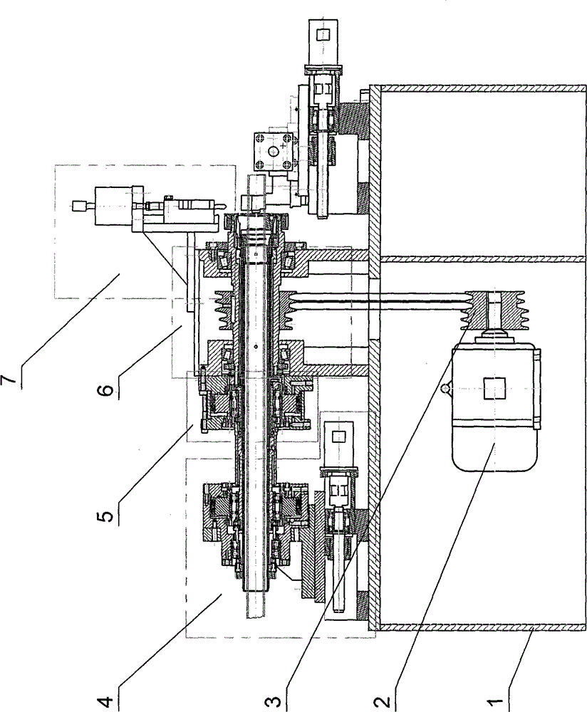
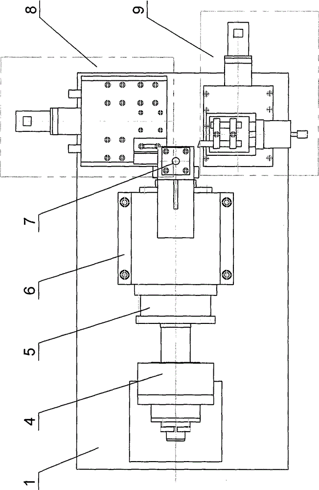
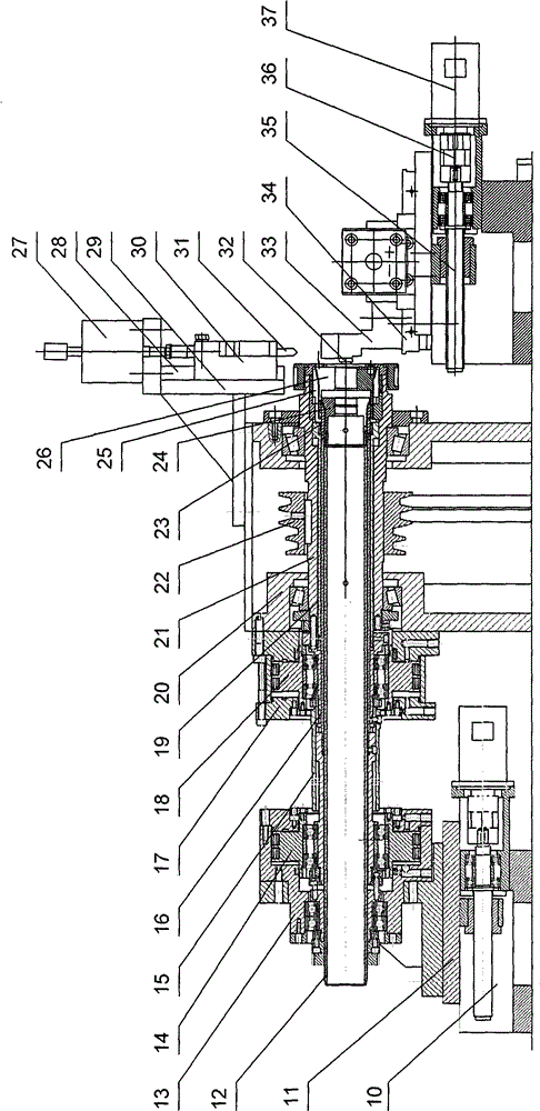
[0020] in figure 1 , figure 2 , image 3 , Figure 4 Among them, the rectangular frame 1 is equipped with a motor 2 in the box, and a driving pulley 3 is provided on the output shaft of the motor 2. The driving pulley 3 is a combination of two reducing diameter double groove pulleys, and the driving pulley 3 is driven by two V-belts. The driven pulley 22 in the device is connected, and four speed changes are realized by moving the position of the motor 2 left and right. The driven pulley 22 is the same as the driving pulley 3, but the installation direction is opposite. The driven pulley 22 is fixed on the main shaft 21, and the main shaft 21 It is arranged inside the spindle box 20, which is set above the frame 1. A tapered roller bearing is provided in the grooves on both sides of the spindle box 20 at both ends of the spindle 21. The spindle 21...


PUM


Abstract

A multifunctional scratch-free pipe cutting machine relates to a special machine tool. The pipe cutting machine is mainly composed of a transmission device, a servo feeding device, a clamping device, a pneumatic chamfering device, a servo pipe cutting device and a servo car outer circle device. The feeding chuck realizes the clamping and loosening of the pipe through the air cylinder. When the servo feeding device moves backward to grasp the pipe, the feeding chuck is loosened, so that the feeding chuck and the surface of the pipe do not contact, thus causing no friction to the surface of the pipe. Scratches, so that the surface of the tube is scratch-free. Through the connection and sliding action of the sliding spline and the pin shaft, the axial relative movement between the components can be realized, and the synchronous rotation of each rotating part can be realized. The pipe cutting machine is controlled by computer PLC, which realizes the integrated automatic processing of the outer circle, chamfering and cutting of the long pipe car, and does not cause friction and scratches on the surface of the pipe. It has high positioning accuracy, good stability, high speed and high efficiency. High, saving labor and production costs.

Description

Technical field [0001] The invention relates to a special machine tool, in particular to a multifunctional non-scratch pipe cutting machine. The product is suitable for cutting and processing oblong steel pipes. Background technique [0002] Since my country's reform and opening up, the national economy has grown rapidly, and "scientific and technological innovation, independent innovation" has become the mainstream of my country's current industrial development. my country's industry has gradually developed in the direction of intensive, energy-saving, emission-reducing, and low-carbon. Pipe cutting machines are widely used in industrial production as pipe cutting equipment. Existing pipe cutting machines generally have two pipe cutting methods: one is that the steel pipe rotates, and the cutter only makes a feed movement. However, due to the long length of the steel pipe raw material, the vibration and noise generated by the rotation are large, and it is difficult to ensure the...

Claims


Application Information

Patent Timeline
IPC IPC(8): B23P23/00B23Q3/08B23Q7/00B23Q5/40
Inventor 王新华
Owner YANCHENG SHUANGJIA ELECTRIC
Features
  • R&D
  • Intellectual Property
  • Life Sciences
  • Materials
  • Tech Scout
  • Unparalleled Data Quality
  • Higher Quality Content
  • 60% Fewer Hallucinations
Learn More