
Horizontal hole or inclined hole drilling tool lifting system

A lifting system and horizontal hole technology, applied in the field of lifting systems, can solve the problems of high resistance of horizontal holes or inclined holes, inability to press drilling tools, high labor intensity, etc., so as to improve efficiency, reduce labor intensity, and work safely and reliably. Effect

Active Publication Date: 2017-12-05
CHONGQING BUREAU OF GEOLOGY & MINERAL EXPLORATION & DEV NO 208 HYDROGEOLOGICAL & ENG GEOLOGICAL TEAM
View PDF6 Cites 0 Cited by
  • Summary
  • Abstract
  • Description
  • Claims
  • Application Information

AI Technical Summary

Problems solved by technology

[0006] 1. Manually conveying or pulling out the drilling tool, due to the large resistance of the horizontal hole or the inclined hole, it needs multiple people to work together, which is extremely labor-intensive, low in efficiency, and unsafe
[0007] 2. The power head (top drive) drilling rig lowers or extracts the drilling tool. Although the labor intensity is low, due to the limited length of the active drill pipe of the drilling rig (generally about 3 meters), only one 3 meters can be drawn out (or fed) each time. Not only is the efficiency extremely low, but also the drill pipe larger than 3 meters cannot be pressed (or pulled out)

Method used


Image

  • Horizontal hole or inclined hole drilling tool lifting system
  • Horizontal hole or inclined hole drilling tool lifting system
  • Horizontal hole or inclined hole drilling tool lifting system

Examples


Embodiment Construction

[0030] Below by embodiment and in conjunction with accompanying drawing, the present invention will be further described:

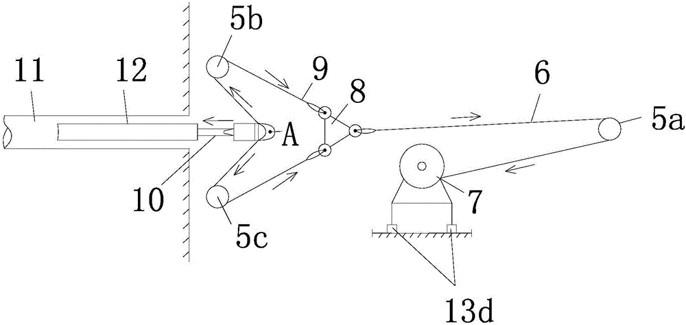
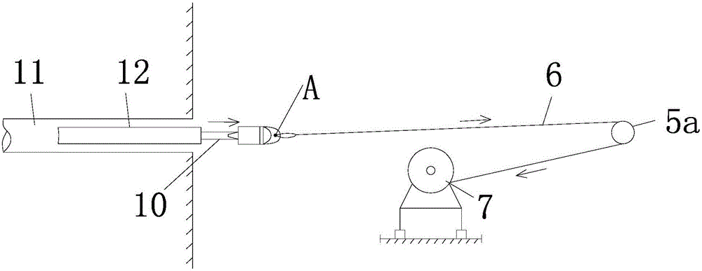
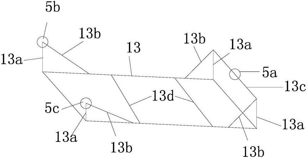
[0031] combine figure 1 — image 3 As shown, a horizontal hole or inclined hole drilling tool lifting system is mainly composed of an underframe 13, a first fixed pulley 5a, a second fixed pulley 5b, a third fixed pulley 5c, a first steel wire rope 6, a second steel wire rope 9, a triangular Connecting ring 8, winch 7 and special joint A etc. are formed.

[0032] The first fixed pulley 5a, the second fixed pulley 5b, and the third fixed pulley 5c are installed above the underframe 13 by respective mounting brackets and arranged in an isosceles triangle on the top view projection, wherein the first fixed pulley 5a is located far away from the borehole One end of 11, the second fixed pulley 5b, the third fixed pulley 5c are of the same height and are located on the side close to the borehole 11. Hoist 7 is installed in the middle part of underframe 13. ...


PUM


Abstract

The invention discloses a lifting system of a horizontal hole or inclined hole drilling tool. A first fixed pulley, a second fixed pulley and a third fixed pulley are installed above a bottom frame, wherein the first fixed pulley is located at the end away from a drilled hole, and the second fixed pulley and the third fixed pulley are equal in height and located on the side close to the drilled hole. A winch is installed in the middle of the bottom frame. When the drilling tool needs to be conveyed to the drilled hole, one end of a first steel wire rope is fixed to the winch, and the other end of the first steel wire rope winds around the first fixed pulley and then is connected with one end of a triangular connecting ring; a second steel wire rope sequentially winds around the second fixed pulley, a notch of a special joint and the fixed pulley, and then the two ends of the second steel wire rope are connected with the other two ends of the triangular connecting ring in a one-to-one corresponding mode; when the drilling tool inside the drilled hole needs to be lifted out of the hole, one end of the first steel wire rope is fixed to the winch, and the other end of the first steel wire rope is arranged on a bolt of the special joint in a sleeving mode. The lifting system can be used for conveying or taking out drilling tools of different lengths, can greatly improve the working efficiency and lower labor intensity of workers, and is convenient to operate, safe, reliable and small in occupied area.

Description

technical field [0001] The invention relates to the field of geological drilling engineering, in particular to a lifting system for lifting and lowering drilling tools during horizontal hole or inclined hole drilling construction. Background technique [0002] At present, there is no special lifting system for lifting and lowering drilling tools for horizontal or inclined holes. The general practice is: [0003] First, when a traditional vertical shaft drilling machine is used, the drilling tool is completely extracted from the hole manually or forced into the hole manually. [0004] Second, when a power head type drilling rig (top drive type drilling rig) is used, the power of the power head is used to press-feed or extract the drilling tools one by one into the hole. [0005] There is a problem: [0006] 1. Manually conveying or pulling out the drilling tool, because the resistance of the horizontal hole or the inclined hole is extremely large, it needs many people to wo...

Claims


Application Information

Patent Timeline
Patent Type & Authority Patents(China)
IPC IPC(8): E21B19/084E21B15/04E21B17/02
CPCE21B15/04E21B17/02E21B19/084
Inventor 任良治
Owner CHONGQING BUREAU OF GEOLOGY & MINERAL EXPLORATION & DEV NO 208 HYDROGEOLOGICAL & ENG GEOLOGICAL TEAM
Learn More