
Dual-polarization dipole unit, antenna and multi-frequency antenna array

A technology of a pole antenna and a dipole antenna, which is applied to antenna arrays, antennas, slot antennas, etc., can solve the problems of complex realization forms and assembly processes, difficult to achieve, and distortion of the working frequency band pattern, and achieves a simple and beautiful structure. Low-profile, easy-to-engineer effects

Active Publication Date: 2019-07-12
SHANGHAI AMPHENOL AIRWAVE COMM ELECTRONICS CO LTD
View PDF6 Cites 1 Cited by
  • Summary
  • Abstract
  • Description
  • Claims
  • Application Information

AI Technical Summary

Problems solved by technology

[0003] Existing base station antennas are mostly implemented with metal die-casting vibrators, which require a complex feed network, such as the need to use 4 coaxial cables to achieve feed, and the implementation form and assembly process are complex
Even if the broadband antenna realized by the PCB printing process, it is difficult to realize the wideband (690-960MHz or 1700-2700MHz) condition under the structure form of low profile (the height between the antenna and the reflector is less than 0.125 wavelengths), and the electrical performance index Meets the requirements of the base station antenna industry standard
In addition, in the multi-frequency antenna, there is obvious mutual coupling between the high and low frequency antennas, which causes the distortion of the pattern of the respective working frequency bands

Method used


Image

  • Dual-polarization dipole unit, antenna and multi-frequency antenna array
  • Dual-polarization dipole unit, antenna and multi-frequency antenna array
  • Dual-polarization dipole unit, antenna and multi-frequency antenna array

Examples


Embodiment Construction

[0044] In order to make the above objects, features and advantages of the present invention more comprehensible, specific implementations of the present invention will be described in detail below in conjunction with the accompanying drawings.

[0045] In the following description, numerous specific details are set forth in order to provide a thorough understanding of the present invention. However, the present invention can be implemented in many other ways different from those described here, and those skilled in the art can make similar extensions without violating the connotation of the present invention, so the present invention is not limited by the specific implementations disclosed below.

[0046] The dual-polarization vibrator unit in the embodiment of the present invention may be made of a printed circuit board, but is not limited thereto. The dual-polarized vibrator unit of the embodiment of the present invention can adopt PCB materials commonly used in common base ...


PUM


Abstract

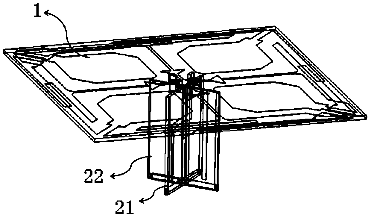
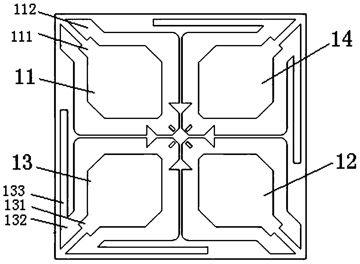
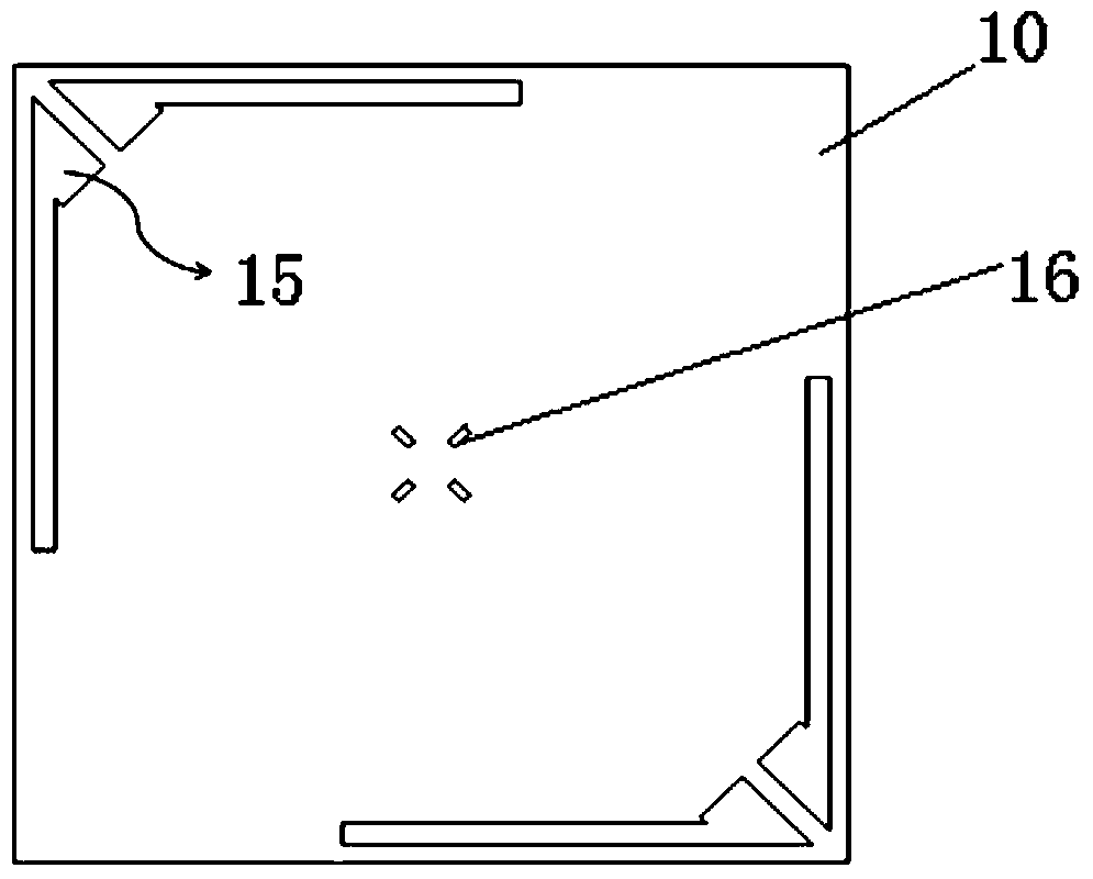
The invention provides a dual-polarized vibrator unit, an antenna and a multi-frequency antenna array. The dual-polarized vibrator unit includes a radiator and a balun support portion for feeding of the radiator. The radiator includes a dielectric substrate, two pairs of dipole antenna arms being disposed on an upper surface of the dielectric substrate and in orthogonal arrangement of plus or minus 45 degrees, and at least one coupling metal strap disposed on a lower surface of the dielectric substrate. Current induction is generated between the dipole antenna arms and the coupling metal strap so that a current path is formed on the coupling metal strap. The vibrator unit and the antenna thereof in the invention can achieve the ultra-broadband, high gain, high efficiency, high cross polarization ratio and high front-ratio, high isolation, low profile and low coupling and is simple and beautiful in structure, easy in engineering realization and suitable for mass production, the production cost is reduced, and the electrical performance index meets the base station antenna industry standard.

Description

technical field [0001] The invention relates to the technical field of antennas, in particular to a dual-polarization dipole unit, an antenna and a multi-frequency antenna array. Background technique [0002] The base station antenna is the electrical bridge between the user terminal and the base station in the air in the mobile communication system. It is the most critical component in the entire antenna feeder system. The quality of the base station antenna directly affects the communication quality. [0003] Existing base station antennas are mostly implemented with metal die-casting vibrators, which require a complex feed network, such as four coaxial cables for feed, and the implementation form and assembly process are complicated. Even if the broadband antenna realized by the PCB printing process, it is difficult to realize the wideband (690-960MHz or 1700-2700MHz) condition under the structure form of low profile (the height between the antenna and the reflector is le...

Claims


Application Information

Patent Timeline
Patent Type & Authority Patents(China)
IPC IPC(8): H01Q1/38H01Q1/36H01Q13/10H01Q21/00
CPCH01Q1/36H01Q1/38H01Q13/10H01Q21/00H01Q21/0006H01Q25/001
Inventor 张凯董孩李
Owner SHANGHAI AMPHENOL AIRWAVE COMM ELECTRONICS CO LTD
Learn More