Motor resolver detection and conditioning circuit and resolver initial position self-detection and self-updating method

A conditioning circuit and voltage conditioning technology, applied in the control of generators, motor-generators, and electromechanical transmissions, etc., can solve the problems of reducing the position accuracy of the motor resolver, not taking it into account, and damage to the resolver decoding chip, etc. The effect of reducing the adjustment link of the resolver position and improving the accuracy

Active Publication Date: 2016-08-24
GUANGZHOU CHENGXING ZHIDONG AUTOMOTIVE TECH CO LTD
View PDF4 Cites 18 Cited by
  • Summary
  • Abstract
  • Description
  • Claims
  • Application Information

AI Technical Summary

Problems solved by technology

However, this method assumes that the voltage amplitude and phase of the resolver and the resolver decoding chip are the same, and does not take into account the inconsistency of the voltage amplitude and phase of the two due to interference, noise and other factors, which reduces the motor rotation. The accuracy of position detection will change, and in severe cases, the resolver decoding chip will be damaged due to the excessive output voltage of the resolver

Method used


Image

  • Motor resolver detection and conditioning circuit and resolver initial position self-detection and self-updating method
  • Motor resolver detection and conditioning circuit and resolver initial position self-detection and self-updating method
  • Motor resolver detection and conditioning circuit and resolver initial position self-detection and self-updating method

Examples


no. 1 example

[0055] In the vector control of the motor, the rotor position angle is obtained through the encoder. The resolver is widely used in the field of electric vehicles because of its convenient start-up and solid material. The main purpose of the initial positioning of the resolver is to obtain the absolute angle of the encoder corresponding to the motor position angle of 0 degrees (that is, the initial angle). According to this information, the position angle of the motor can be one-to-one corresponding to the absolute angle of the encoder.

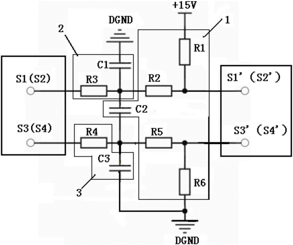
[0056] The motor controller of the present invention follows the principle of the prior art when reading the absolute angle of the encoder through the resolver, the decoding chip and the peripheral circuit: the excitation signal generated by the resolver decoding chip is output to the resolver through the excitation signal conditioning circuit, Then the resolver sends the detected resolver SIN signal and resolver COS signal to the decoding ch...

no. 2 example

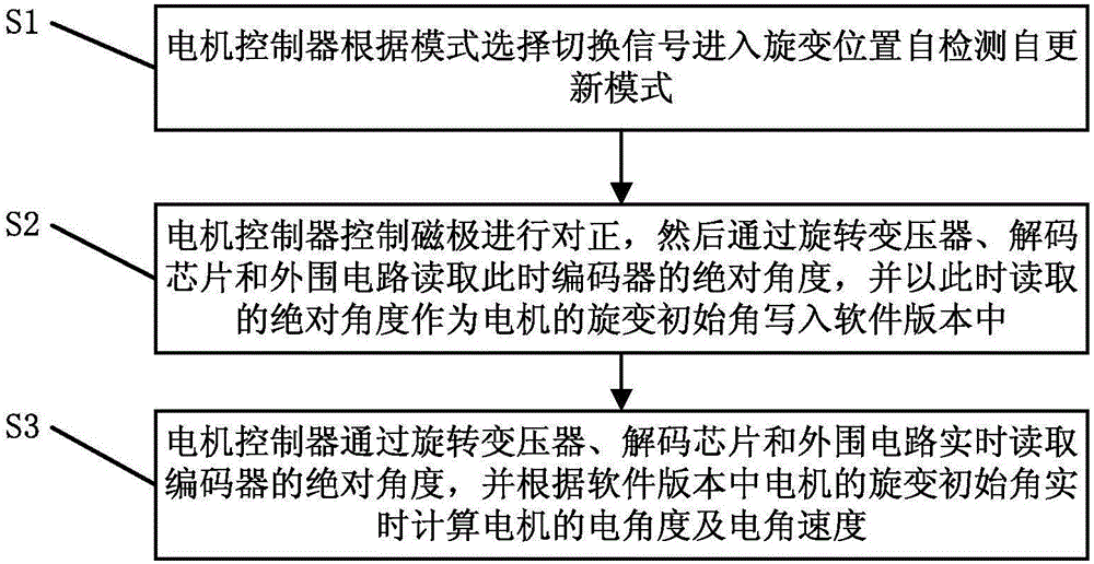
[0063] In order to solve the problem of the deviation of the initial position parameters of the motor resolver caused by the requirement of consistent software versions under the premise that the consistency of the resolver is difficult to guarantee in the production of batch motor systems, the present invention proposes a method for self-detection and self-update of the resolver initial position . The realization principle of the self-detection and self-renewal method of the present invention is as follows:

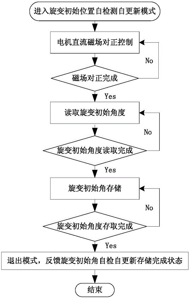
[0064] The invention is equipped with a motor resolver initial angle detection mode. During the factory inspection of the motor system, the motor controller can enter this mode through communication commands (such as CAN communication commands), automatically align the direction of the motor magnetic field, and record and store the resolver angle at this time. , as the initial angle of the resolver fixed by other subsequent control functions, which includes:

[0065] a)...


PUM


Abstract

The invention discloses a motor resolver detection and conditioning circuit and a resolver initial position self-detection and self-updating method. The method comprises the steps that a motor controller enters a resolver position self-detection and self-updating mode according to a mode selection switching signal; the motor controller controls the alignment of magnetic electrodes, then reads out the absolute angle of an encoder at the moment through a rotary transformer, an encoder chip and a peripheral circuit, uses the absolute angle read out at the moment as the resolver initial angle of the motor, and writes into a software version; and the motor controller reads out the absolute angle of the encoder in real time through the rotary transformer, the encoder chip and the peripheral circuit, and calculates the electrical angle and electrical angle speed of the motor in real time according to the resolver initial angle of the motor in the software version. By adding the resolver position self-detection and self-updating mode, the invention can effectively reduce the resolver position adjustment link in the motor factory test under the premise of the same software version, and can automatically and accurate detect and update the resolver initial angle. The invention can be widely applied to the field of frequency control.

Description

technical field [0001] The invention relates to the field of frequency conversion and speed regulation, in particular to a motor resolver detection and conditioning circuit and a resolver initial position self-detection and self-renewal method. Background technique [0002] The current position of the motor operation is critical to the vector control of the motor system. Existing schemes obtain the current position of the motor through a motor position sensor or an estimation method, and calculate the motor speed in conjunction with the sampling (or estimation) period. First, the accuracy of existing estimation methods cannot match the accuracy of sensor calculations. Secondly, in the existing motor position sensor method, the initial angle position of the resolver has been calibrated in the software, and the accuracy can only be guaranteed by positioning and installing the resolver position. However, there is a difference between the actual resolver position and the calib...

Claims


Application Information

Patent Timeline
Patent Type & Authority Applications(China)
IPC IPC(8): H02P21/18
Inventor 王光宇何涛夏珩
Owner GUANGZHOU CHENGXING ZHIDONG AUTOMOTIVE TECH CO LTD
Why Eureka
Try Eureka