A biological cell ultrasonic atomic force microscopy detection system and method

A technology of atomic force microscopy and biological cells, applied in the direction of using ultrasonic/sonic/infrasonic waves, measuring devices, instruments, etc., can solve damage, fail to fully reflect the acoustic characteristics of living cells, lack research methods, ultra-micro internal structure analysis methods, etc. problem, to avoid damage

Active Publication Date: 2018-06-19
CHANGCHUN UNIV OF SCI & TECH
View PDF4 Cites 1 Cited by
  • Summary
  • Abstract
  • Description
  • Claims
  • Application Information

AI Technical Summary

Problems solved by technology

When measuring, TEM needs to cut the sample to the thickness that electrons can penetrate, generally only tens of nanometers, so the cells need to be sliced, which will also destroy the cells
In 2009, DeJonge et al. of the University of Southern California used scanning transmission electron microscopy (STEM) to successfully image the submicroscopic structure of COS7 fibroblasts in a liquid environment. layer, which is a destructive measurement
In 2009, Zhang Bo, Cheng Qian and others from Tongji University combined the atomic force microscope with a self-made frequency conversion acoustic excitation platform to study the acoustic image characteristics of rat aortic smooth muscle cells. characteristic
[0004] Due to the low rigidity of cells, and the difficulty in conducting nanoscale nondestructive testing of biological living cells in physiological environments, especially for internal structure detection and imaging, there is still a lack of effective research methods to achieve nanoscale ultrafine internal structure analysis methods.

Method used


Image

  • A biological cell ultrasonic atomic force microscopy detection system and method
  • A biological cell ultrasonic atomic force microscopy detection system and method
  • A biological cell ultrasonic atomic force microscopy detection system and method

Examples


Embodiment Construction

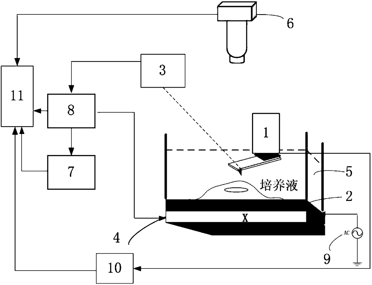
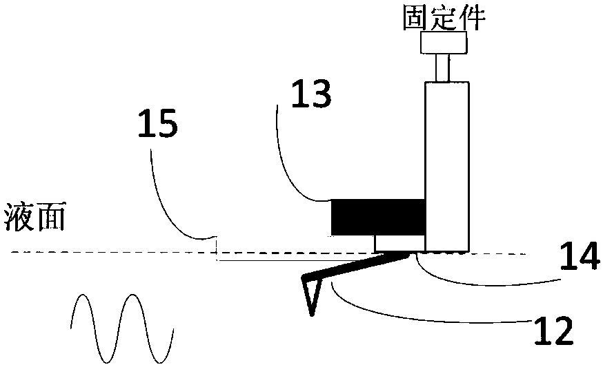
[0029] Such as figure 1 As shown, the biological cell ultrasonic atomic force microscopic detection system of the present invention includes a detector 1, a piezoelectric transducer 2, a probe displacement detection module 3, a three-dimensional displacement platform 4, a liquid pool 5, an optical microscope 6, and a lock-in amplifier circuit 7 , a probe control module 8, a signal generator 9, an ultrasonic ranging module 10 and a display module 11; the biological cells to be measured are placed in a liquid pool 5 filled with culture fluid, and the liquid pool 5 is placed on the piezoelectric transducer 2 , the piezoelectric transducer 2 is connected with the signal generator 9 for transmitting ultrasonic signals, a three-dimensional displacement platform 4 is installed under the piezoelectric transducer 2, and the three-dimensional displacement platform 4 can move in the XYZ direction for controlling the probe 12 Scanning direction, the detector 1 is placed above the biologic...


PUM


Abstract

The invention relates to an ultrasonic atomic force microscopic detection system and method for biological cells in a physiological environment, which is composed of a detector, a piezoelectric transducer, a probe control module, a lock-in amplifier, an ultrasonic ranging module and the like. The detector is placed in a physiological environment to scan biological cells, while the piezoelectric transducer vibrates at an ultrasonic frequency. The ultrasonic signal passes through the biological cells to generate different signal responses. The system collects the response signals to obtain the morphology and internal map of the biological cells. Ultrasonic The echo time-delay signal recorded and processed by the distance measurement module quantitatively characterizes the sound path in the vertical direction to reconstruct the depth map of biological cells. The invention can analyze the ultramicro internal structure of biological cells at the nanoscale, precisely position and guide probes to inject nano drug-loaded particles into cancer cells, and observe the stress changes in their morphology and internal structure, and can be used in living cells in physiological environments Non-destructive measurement at the nanoscale has guiding significance for nanobiotechnology and nanomedicine.

Description

technical field [0001] The invention relates to a biological cell ultrasonic atomic force microscopic detection system and method, and is especially suitable for the non-destructive measurement of the nanoscale internal structure of cells in a physiological environment. Background technique [0002] With the development of nanotechnology, atomic force microscopy (AFM) has become one of the most important nanotechnology. Because of its wide working range, its application prospect is extremely wide, especially in the field of biomedicine, which has important research value. [0003] At the nanoscale, the properties and behaviors of biological samples and materials are not only related to their surface structures, but also to their internal structures. In today's technology, transmission electron microscope (TEM) is the main measurement technique for imaging internal structures. When measuring, TEM needs to cut the sample to the thickness that electrons can penetrate, generall...

Claims


Application Information

Patent Timeline
Patent Type & Authority Patents(China)
IPC IPC(8): G01B17/06
CPCG01B17/06
Inventor 王作斌刘妍田立国赵玉静董莉彤宋正勋翁占坤许红梅
Owner CHANGCHUN UNIV OF SCI & TECH
Why Eureka
Try Eureka