Electromagnetic field positioning method of overhead transmission line patrol unmanned aerial vehicle and apparatus thereof
A technology for overhead transmission lines and line inspection unmanned aerial vehicles, which is applied in electromagnetic field characteristics, three-dimensional position/channel control, non-electric variable control and other directions, can solve problems such as electronic instrument interference, three-dimensional imaging errors, and personal safety threats to staff. To achieve the effect of improving accuracy and improving the degree of automation
- Summary
- Abstract
- Description
- Claims
- Application Information
AI Technical Summary
Problems solved by technology
Method used
Image

Examples
Embodiment
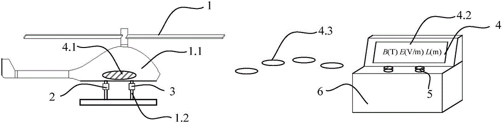
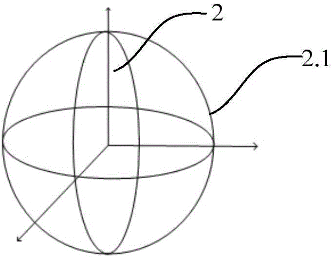
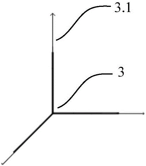
[0058] according to figure 2 Make the magnetic field vector measuring device 2 as shown, according to image 3 Make the electric field vector measuring device 3 as shown; The magnetic field vector measuring device 2 and the electric field vector measuring device 3 are respectively installed on the bracket 1.2 of the drone 1; the magnetic field vector measuring device 2 and the electric field vector measuring device 3 are connected to the wireless network The transmitting device 4.1 of the transmission device 4, and the transmitting device 4.1 of the wireless transmission device 4 is installed in the fuselage 1.1 of the drone 1; the receiving device 4.2, the alarm device 5, and the terminal control system 6 of the wireless transmission device 4 are installed in the Ground control room.
[0059] Start the UAV 1 to fly to the vicinity of the transmission line 7, measure the magnetic field vector 8 and the electric field vector 9 at the position of the UAV 1 at this time, and ca...
PUM
 Abstract
Description
Claims
Application Information