Captive flight system and captive flight vehicle thereof

An aircraft and tethering technology, which is applied in the field of aircraft, can solve the problems of aircraft flight height and range limitations, and achieve the effect of achieving long endurance, reducing load, and improving lift and load capacity

Inactive Publication Date: 2016-09-07
苏跃进 +2
View PDF10 Cites 13 Cited by
  • Summary
  • Abstract
  • Description
  • Claims
  • Application Information

AI Technical Summary

Problems solved by technology

[0004] The purpose of the present invention is to provide a tethered aircraft to solve the technical problem that the aircraft in the prior art needs to rely on the power transmission cable for power supply and the flight height and range of the aircraft are limited

Method used


Image

  • Captive flight system and captive flight vehicle thereof
  • Captive flight system and captive flight vehicle thereof
  • Captive flight system and captive flight vehicle thereof

Examples


Embodiment 2

[0038] Embodiment 2 of the tethered flight system of the present invention: as Image 6 As shown, the difference from Embodiment 1 is that the fuselage is also provided with a docking piece for docking with the aerostat platform so as to charge the aircraft 1 through the power supply on the aerostat platform, and the power supply is arranged on the anchorage ground. On the empty container 5. The docking part is a docking ring 14, and the docking ring 14 and the docking hook 51 provided on the aerostat platform can be docked and connected. The connecting ring 14 and the connecting hook 51 are provided with a charging interface. The aerostat platform becomes the aerial charging pile of the aircraft. After charging, the aircraft can enter the free flight state again, and the aircraft does not need to perform repeated take-off and landing operations, thus realizing long-duration free flight. In the case of multiple aerostat platforms, the aircraft can choose to dock at the neare...

Embodiment 3

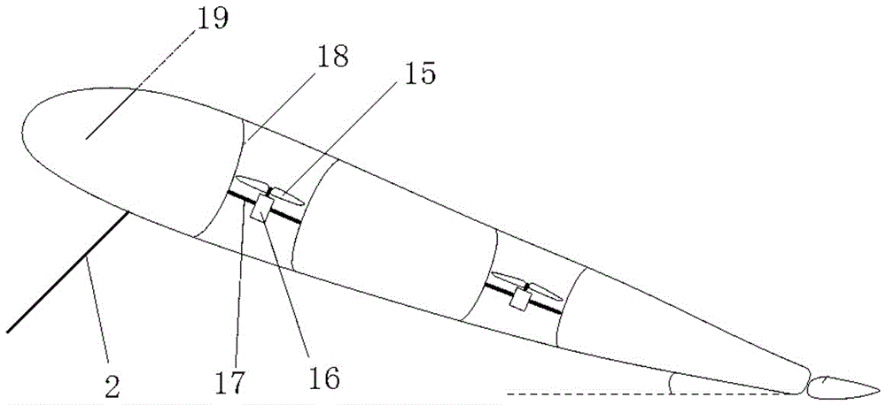
[0044] Embodiment 3 of the tethered flight system of the present invention: as Figure 7 As shown, the difference with Embodiment 1 is that the fuselage is also provided with a vertical duct 6, and the rotor includes a vertical rotor 7, and the vertical duct 6 is provided with a motor and a vertical rotor 7, and the rotation axis of the vertical rotor is in line with the horizontal axis. The axis of rotation of rotor 15 is vertical. There are two vertical rotors 7 and two horizontal rotors 15 respectively.

[0045] Under the fixed-point resident flight state, the fixed-wing flight maintains a certain angle of attack, the air pressure above the fixed-wing of the aircraft is less than the pressure below, and the wind passes through the horizontal duct 18, and the wind power promotes the rotation of the horizontal rotor 15 of the horizontal duct 18, and the motor Driven by the torque generated by the horizontal ducted horizontal rotor, it is controlled to be in the generator sta...


PUM


Abstract

The invention discloses a captive flight system and a captive flight vehicle thereof. The captive flight vehicle comprises a fuselage, a fixed wing and rotor wings, and further comprises motors used for driving the rotor wings to rotate. Each motor have two working modes, namely the electric motor mode and the electric motor mode. In the electric generator mode, the motors drive the rotor wings to rotate so as to generate driving force, and in the electric generator mode, the rotors reversely drive the motors to generate electricity under the action of wind. The flight vehicle in the design has the electricity self-generation function, a power cable can be omitted with respect to a captive cable, and therefore the load on the captive cable is reduced substantially, and the voltage drop problem and the transmission loss problem of the cable are avoided. In the captive state, the lift force and load bearing capacity can be enhanced substantially, and thus the long endurance and high ceiling are achieved.

Description

technical field [0001] The invention relates to the field of aircraft, in particular to a tethered flight system and a tethered aircraft. Background technique [0002] Parameters such as the flight time, flight height, load capacity, and electric power of the load of the electric rotorcraft are all subject to the power supply. In order to improve the flight time of the aircraft and save energy, many aircraft designs currently adopt the combination of rotor and fixed wing, and operate according to the vertical take-off and landing mode during lifting operations; during level flight operations, rely on the lift generated by the fixed wings to maintain afloat However, the energy of the aircraft is limited, and the problem of short time in the air is still outstanding. [0003] For electric rotorcraft, the problem of short time in the air can be solved by photoelectric composite cable tethering. The system includes the aircraft, a tether and a ground unit, and the tether conne...

Claims


Application Information

Patent Timeline
Patent Type & Authority Applications(China)
IPC IPC(8): B64C27/20B64C27/26B64F1/12
CPCB64C27/20B64C27/26B64F1/12B64U10/13B64U50/19
Inventor 苏跃进苏寄闲王胜春
Owner 苏跃进
Why Eureka
Try Eureka