Planar gate IGBT and manufacturing method therefor
A planar gate and gate electrode technology, which is applied in the field of insulated gate bipolar transistors and planar insulated gate bipolar transistors, can solve the problems of electromagnetic radiation, increase switching loss of devices, and reduce switching speed of devices.
- Summary
- Abstract
- Description
- Claims
- Application Information
AI Technical Summary
Problems solved by technology
Method used
Image
Examples
Embodiment 1
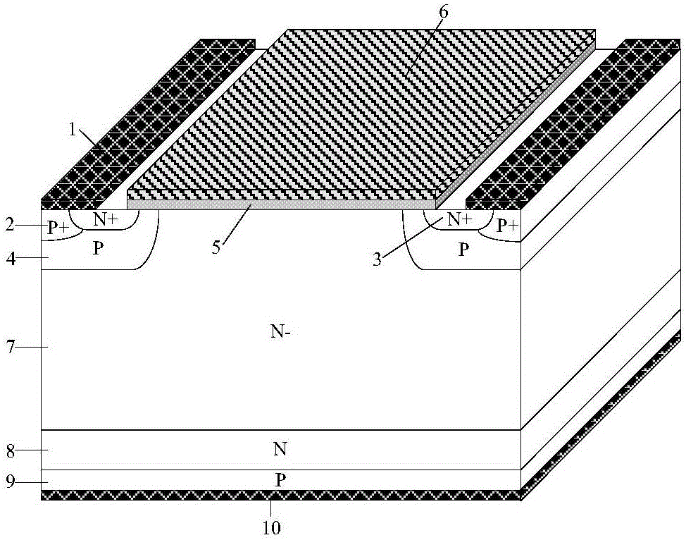
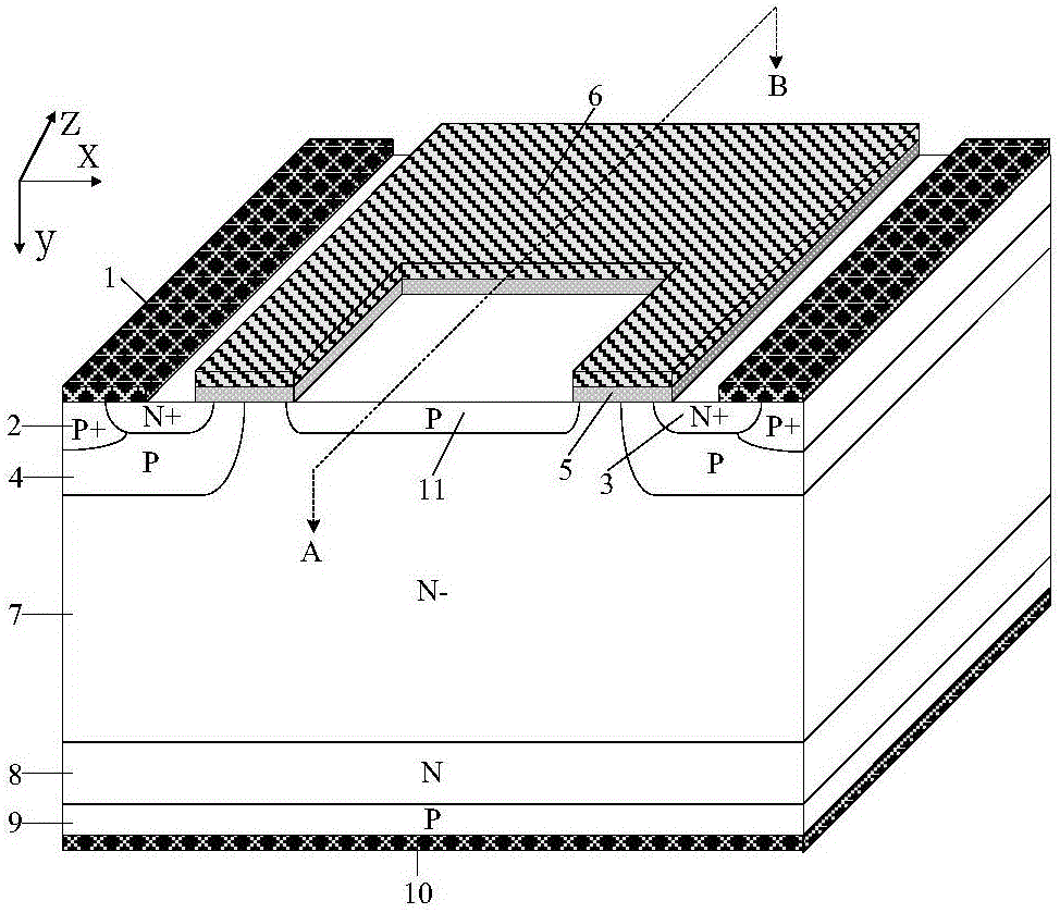
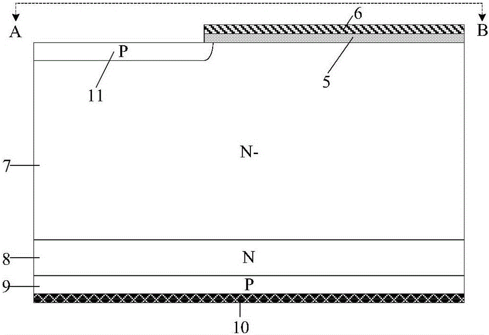
[0044] A planar gate IGBT, its semi-cellular structure and the section along the AB line are as follows figure 2 with image 3 As shown, it includes: the back collector metal 10, the P-type collector region 9 located on the back collector metal 10 and connected to it, the N-type field stop layer 8 located on the P-type collector region 9 and connected to it, The N-drift region 7 located on the N-type field stop layer 8 and connected to it; the p-type base region 4 located on both sides of the upper part of the N-drift region 7 and connected to it, and the upper part of the p-type base region 4 and connected to each other Independent N+ emitter region 3 and P+ emitter region 2; emitter metal 1 located on the upper surface of N+ emitter region 3 and P+ emitter region 2; compound gate structure and floating p-type region located on the semiconductor surface between emitter metal 1 11. It is characterized in that: the composite gate structure includes a dielectric layer 5 and a ...
Embodiment 2
[0046] A planar gate IGBT, its semi-cellular structure and the cross-section along the AB and CD lines are as follows Figure 4 , Figure 5 with Image 6 As shown, on the basis of Embodiment 1, the gate electrode 6 also has a left-right symmetrical interdigitated finger at the center of the half-cell in the direction perpendicular to the length of the MOS channel. The length of the interdigitated fingers in the direction parallel to the length of the MOS channel is 3-5 microns, and the length in the direction perpendicular to the length of the MOS channel is 5-10 microns. The presence of the interdigitated fingers of the gate electrode 6 further enhances the lateral carrier diffusion from the gate to the emitter connection electrode, improving forward conduction characteristics and carrier concentration distribution.
Embodiment 3
[0048] A planar gate IGBT, its semi-cellular structure and the cross-section along the AB and CD lines are as follows Figure 7 , Figure 8 with Figure 9 As shown, on the basis of Example 2, there is also a layer of N-type N-type on the surface of the JFET region between the floating P-type regions 11, both sides of the floating P-type regions 11 and the p-type base region 4. Layer 12, the doping concentration of the N-type layer 12 is greater than the concentration of the N-drift region 7, and its junction depth is 0.1-0.3 microns smaller than the junction depth of the floating P-type region 11. The introduction of the N-type buried layer 15 further improves the forward conduction characteristics and carrier concentration distribution of the device. When the device breaks down, the N-type buried layer 15 is fully depleted.
PUM
 Abstract
Description
Claims
Application Information
 - R&D
- Intellectual Property
- Life Sciences
- Materials
- Tech Scout
- Unparalleled Data Quality
- Higher Quality Content
- 60% Fewer Hallucinations
Browse by: Latest US Patents, China's latest patents, Technical Efficacy Thesaurus, Application Domain, Technology Topic, Popular Technical Reports.
© 2025 PatSnap. All rights reserved.Legal|Privacy policy|Modern Slavery Act Transparency Statement|Sitemap|About US| Contact US: help@patsnap.com


