Dual-polarization multifunctional device based on anisotropic super-surface, and design method

An anisotropic, metasurface technology, applied in the field of dual-polarization multi-function devices, can solve the problems of limited linear gradient dual-polarization manipulation, unseen dual-polarization manipulation, etc.

Active Publication Date: 2016-09-07
AIR FORCE UNIV PLA
View PDF3 Cites 26 Cited by
  • Summary
  • Abstract
  • Description
  • Claims
  • Application Information

AI Technical Summary

Problems solved by technology

However, the existing literature is limited to the dual-polarization control of linear gradients, and no dual-polarization control of parabolic gradients and other more complex phase gradients has been seen so far.

Method used


Image

  • Dual-polarization multifunctional device based on anisotropic super-surface, and design method
  • Dual-polarization multifunctional device based on anisotropic super-surface, and design method
  • Dual-polarization multifunctional device based on anisotropic super-surface, and design method

Examples


Embodiment 1

[0045] Embodiment 1: Single-beam-four-beam dual-polarization highly directional antenna

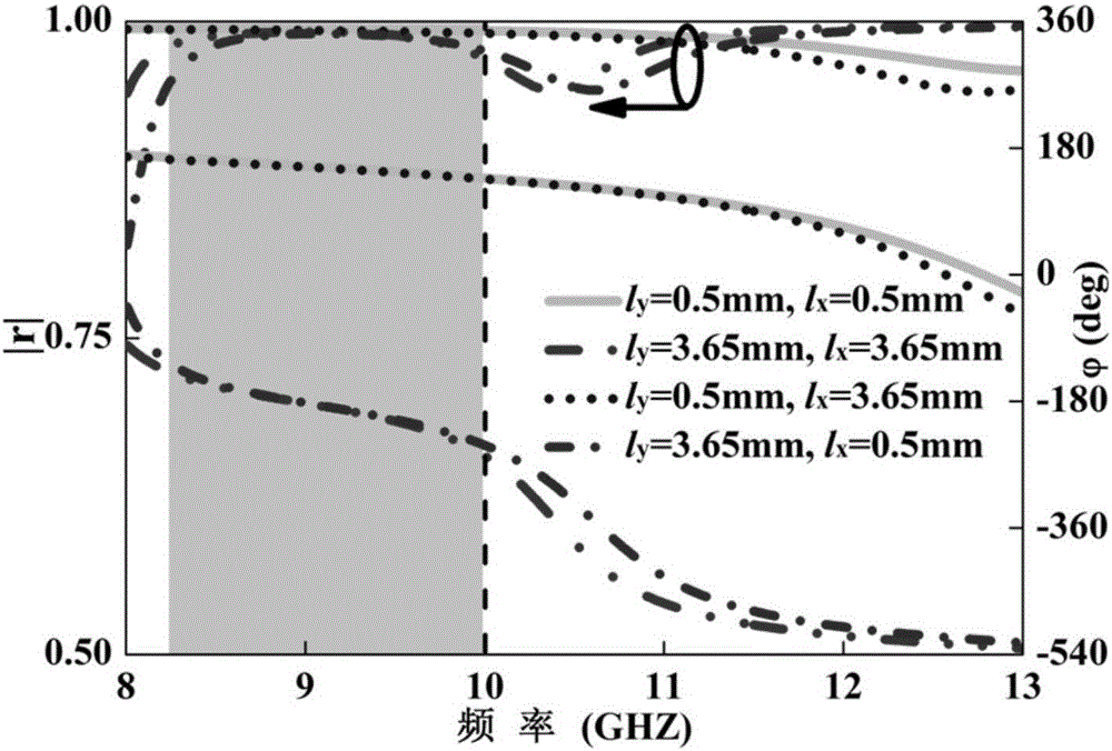
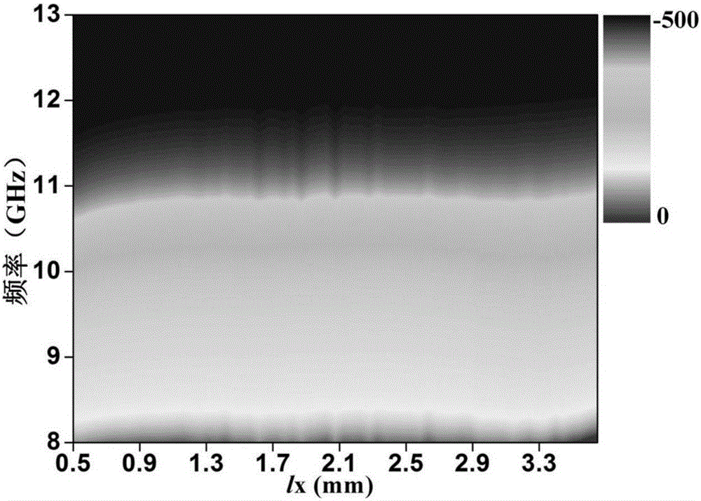
[0046] The design process of single-beam-four-beam dual-polarization highly directional antenna is detailed in the design method of dual-polarization multifunctional device, and the final aperture phase distribution is as follows Figure 7 As shown, where the x-polarized microstrip array aperture is a parabolic phase distribution, and the y-polarized microstrip array aperture is a four-beam phase distribution. Here the four-beam aperture phase distribution is based on the pre-determined feed position F =224.1*0.56=125.5mm, the central operating frequency of the microstrip reflectarray f 0 =10GHz, aperture size D =27*8.3=224.1mm, the number of units N*N =27*27 and the space elevation angle of the four beams θ and azimuth φ And it is obtained by optimizing with alternating projection algorithm. Here the metasurface element adopts the above-mentioned anisotropic metasurface unit, an...

Embodiment 2

[0050] Example 2: Beam deflection - four-beam dual-polarization highly directional antenna

[0051] The design process of beam deflection-four-beam dual-polarization highly directional antenna is detailed in the design method of dual-polarization multifunctional devices, and the final aperture phase distribution is as follows Figure 12 As shown, where the x-polarized metasurface has a linear phase distribution along the x direction, and the superunit is composed of N s=7 units and the linear phase gradient at 10GHz is 60°, the super period is 49.8mm, the theoretical beam deflection angle can be calculated as ,in lambda p is the wavelength at the working frequency; the phase distribution of the four beams on the metasurface under the y-polarization, the antenna contains N*N =31*31 anisotropic metasurface units, the aperture size is D =257.3*257.3mm 2 , the feed location is F =257.3*0.6=154.4mm, the center working frequency is f 0 =10GHz, the spatial position of the f...


PUM


Abstract

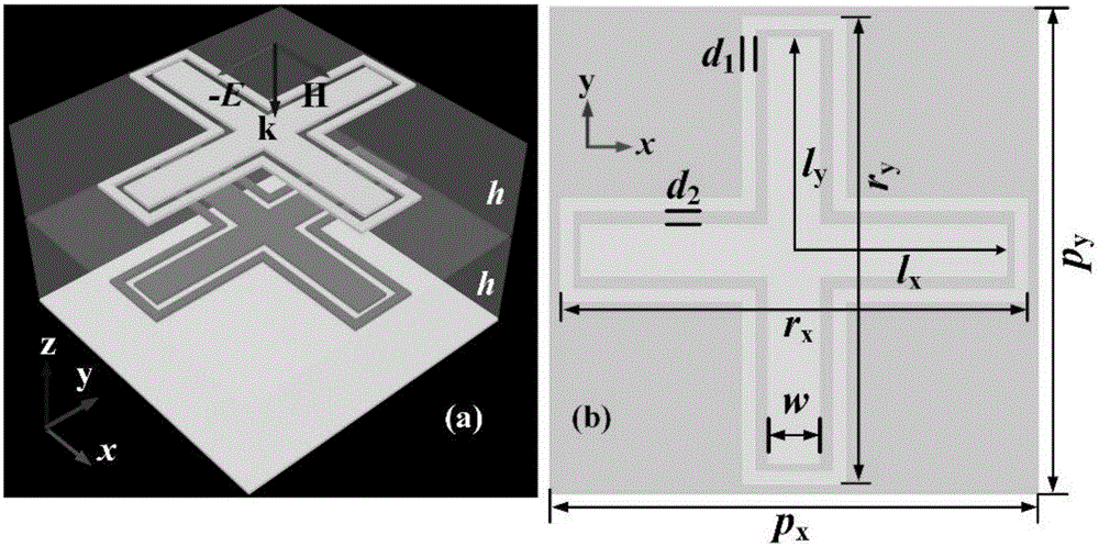
The invention belongs to the technical field of dual-polarization multifunctional devices, and specifically relates to a dual-polarization multifunctional device based on an anisotropic super-surface, and a design method. The device consists of a feed source and the anisotropic super-surface. The distance between the feed source and the anisotropic super-surface is F, and the projection of the feed source on the anisotropic super-surface is located at the center of the anisotropic super-surface. The anisotropic super-surface consists of N*N anisotropic super-surface units, wherein the size parameters of the anisotropic super-surface units are different from each other. Each anisotropic super-surface unit consist of an upper composite metal structure, a lower composite metal structure, two dielectric plates and a bottom metal back plate, wherein the upper and lower composite metal structures are completely the same, and the height of each dielectric plate is h. The composite metal structures are respectively formed by the nesting of a cross-shaped paster in a cross-shaped ring. The device takes the lead in synthesizing a four-beam phase gradient and a paraboloid gradient and synthesizing a four-beam phase gradient and a linear gradient based on the anisotropic super-surface, and achieves the multifunctional and complex electromagnetic wave regulation and control.

Description

technical field [0001] The invention belongs to the technical field of dual-polarization multifunctional devices, and in particular relates to a dual-polarization multifunctional device based on anisotropic metasurfaces and a design method. Background technique [0002] After more than ten years of development, metamaterial (MTM) has developed into a rich system with multiple branches and a very complete concept. Although electromagnetic waves can be manipulated arbitrarily through three-dimensional metamaterials, the high loss and complicated preparation process greatly affect the Its application and promotion are limited. As a two-dimensional planar form of metamaterials, Metasurface (Metasurface) was born accordingly. Due to its planar structure and unique electromagnetic properties, it can conform to high-speed targets such as aircraft, missiles, rockets and satellites without destroying its shape. The characteristics of structure and aerodynamics have been favored and ...

Claims


Application Information

Patent Timeline
Patent Type & Authority Applications(China)
IPC IPC(8): H01Q15/24
CPCH01Q15/244
Inventor 许河秀蔡通王光明庄亚强
Owner AIR FORCE UNIV PLA
Why Eureka
Try Eureka