Steel strip variable-frequency transmission system of steel strip type reduction furnace

A technology of frequency conversion drive and reduction furnace, which is applied in the direction of furnace, furnace type, transportation and packaging, etc., can solve the problems affecting iron powder reduction quality and work efficiency, uneven operation of steel belt, complex transmission structure, etc., to achieve photoelectric integration Control, uniform moving speed, high transmission efficiency

Inactive Publication Date: 2016-09-14
孙颖
View PDF6 Cites 1 Cited by
  • Summary
  • Abstract
  • Description
  • Claims
  • Application Information

AI Technical Summary

Problems solved by technology

At present, the power components in the steel belt reduction furnace are mainly composed of a motor and a reducer. The reducer is fixedly connected to the motor. The output shaft of the reducer is equipped with a pulley, and the drive shaft of the driving roller part is also equipped with a corresponding pulley. The power part drives the active roller part through the belt transmission. Although this driving method is stable and noiseless, and can cushion and absorb shocks, the transmission structure is complicated. If overload and the elastic deformation of the belt drive itself during work will cause the belt and pulley The sliding between the belts makes the movement of the belt in an unstable state, the efficiency drops sharply, the transmission efficiency is low, and the steel belt runs unstable, which seriously affects the quality of iron powder reduction and work efficiency.
Due to the complex transmission structure, it is difficult to correct the deviation of the steel belt during operation

Method used


Image

  • Steel strip variable-frequency transmission system of steel strip type reduction furnace
  • Steel strip variable-frequency transmission system of steel strip type reduction furnace
  • Steel strip variable-frequency transmission system of steel strip type reduction furnace

Examples


Embodiment Construction

[0015] The present invention will be further described below according to the accompanying drawings and in conjunction with the embodiments.

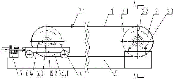
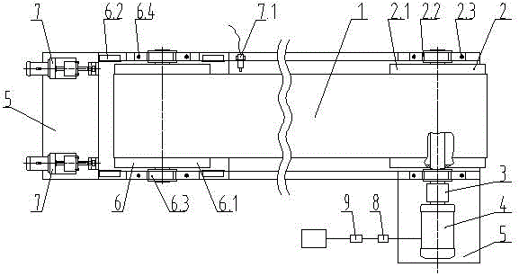
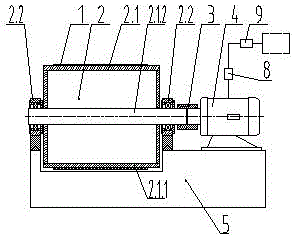
[0016] The steel belt frequency conversion transmission system of the steel belt reduction furnace shown in the attached figure is set in the steel belt reduction furnace, including the steel belt 1, the driving roller part 2, the driven roller part 6, the bracket part 5, and the frequency conversion speed regulating motor 4 , coupling 3; the driving roller part 2 is fixed on the plane at one end of the bracket part 5, and the driven roller part 6 is rollingly supported on the plane at the other end of the bracket part 5; the driving roller part 2 includes the driving roller 2.1, the bearing seat I2.2, Bolt fastener I 2.3; driving roller 2.1 includes roller 2.1.1, driving shaft 2.1.2, driving shaft 2.1.2 runs through the two end plates of roller 2.1.1 and is welded to the two end plates of roller 2.1.1 The driving roller 2.1 is fixed; t...


PUM


Abstract

The invention discloses a steel strip variable-frequency transmission system of a steel strip type reduction furnace, which is arranged in the steel strip type reduction furnace. The steel strip variable-frequency transmission system comprises a steel strip, a driving roller part, a driven roller part, a bracket part and a variable-frequency speed adjusting motor; the driving roller part is provided with a driving roller, and is fixedly connected to the upper plane of one end of the bracket part; the driven roller part includes a driven roller and a movable roller frame, and is supported on the upper plane of the other end of the bracket part in a rolling manner; the steel strip surrounds the outer walls of the driving roller and the driven roller; the variable-frequency speed adjusting motor drives the driving roller to move forwards at uniform speed; one end of the driving roller is coaxially connected with the variable-frequency speed adjusting motor through a coupling; a control loop of the variable-frequency speed adjusting motor is provided with a frequency converter and a program controller, and is electrically connected with a control system of the reduction furnace; and steel strip rectifying devices are respectively arranged in two positions symmetrical corresponding to conveying center axis on the left side of the driven roller part. The steel strip variable-frequency transmission system adopts the frequency converter to adjust the speed in a stepless manner, and is simple in transmission structure, stable in operation and excellent in protecting performance.

Description

technical field [0001] The invention relates to the technical field of technical equipment for the powder metallurgy industry, in particular to a reduction furnace steel belt frequency conversion drive system. Background technique [0002] The steel belt transmission system in the steel belt reduction furnace mainly includes steel belt, power part, driving roller part and driven roller part; One end: the steel belt wraps around the outer wall of the driving roller and the driven roller, and the driving roller and the driven roller are driven by the power part to move forward at a constant speed. At present, the power components in the steel belt reduction furnace are mainly composed of a motor and a reducer. The reducer is fixedly connected to the motor. The output shaft of the reducer is equipped with a pulley, and the drive shaft of the driving roller part is also equipped with a corresponding pulley. The power part drives the active roller part through the belt transmiss...

Claims


Application Information

Patent Timeline
Patent Type & Authority Applications(China)
IPC IPC(8): B22F1/00F27B9/24F27B9/40
CPCF27B9/243F27B9/40B22F1/145
Inventor 孙颖
Owner 孙颖
Why Eureka
Try Eureka