
Conveying device of chips dried by vacuum dry air

A conveying device and vacuum drying technology, applied in drying, gas treatment, drying solid materials, etc., can solve problems such as abnormal spinning, softening and sticking of slices, and blockage of conveying pipes, so as to achieve uniform product quality, smooth spinning process, Dust reduction effect

Inactive Publication Date: 2016-09-14
张家港新丝纬化纤有限公司
View PDF10 Cites 2 Cited by
  • Summary
  • Abstract
  • Description
  • Claims
  • Application Information

AI Technical Summary

Problems solved by technology

However, for low-melting polyester chips, that is, special polyester chips with a melting point lower than 256°C, during the positive pressure conveying process of compressed air, on the one hand, the chip particles collide and rub against each other, and the chip particles and the conveying pipeline, while A large amount of dust is generated, and the temperature of the sliced ​​particles and dust increases due to friction, and due to the large surface area of ​​the dust, the temperature rise changes the internal molecular structure, resulting in a large change in its physical properties such as crystallinity and melting point. The difference is very large, and it is mixed with the slices, resulting in abnormal spinning; on the other hand, because the melting point of some low-melting point slices is as low as 110--130 ° C, its softening point is about 56--62 ° C, during the transportation process It causes the temperature of the sliced ​​particles to rise, causing the slices to soften, stick and agglomerate, and then block the conveying pipeline, making it impossible to continuously convey the slices, resulting in a serious accident of the production line shutting down

Method used


Image

  • Conveying device of chips dried by vacuum dry air

Examples


Embodiment Construction

[0014] The technical solutions in the embodiments of the present invention will be described in detail below in conjunction with the accompanying drawings in the embodiments of the present invention. Obviously, the described embodiments are only some of the embodiments of the present invention, not all of them. Based on the embodiments of the present invention, all other embodiments obtained by persons of ordinary skill in the art without making creative efforts belong to the protection scope of the present invention.

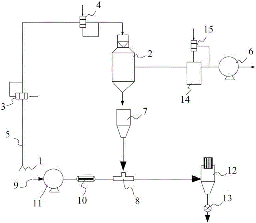
[0015] combine figure 1 As shown, the vacuum dry air dry chip conveying device includes a pipeline purge valve group 3 and a vacuum valve group 4 sequentially arranged between the chip suction port 1 and the drying tower 2, the chip suction port 1, and the pipeline purge valve group 3. The vacuum valve group 4 and the feed port of the drying tower 2 are connected through the slice conveying pipeline 5, the side wall of the drying tower 2 is connected with the e...


PUM


Abstract

The invention discloses a conveying device of chips dried by vacuum dry air. The device comprises a pipeline purging valve unit and a vacuum valve unit which are successively arranged between a chip sucking opening and a drying tower, wherein the chip sucking opening, the pipeline purging valve unit and the vacuum valve unit communicate with a feeding opening of the drying tower via a chip conveying pipeline; the side wall of the drying tower communicates with an external vacuumizing fan; a discharging opening of the drying tower communicates with a mixing bin; a discharging opening of the mixing bin communicates with one inlet of a mixer; a cooler and an air blower are successively arranged between the other inlet of the mixer and a nitrogen gas inlet; the outlet of the mixer communicates with a bag-type dust remover; and a discharging valve is arranged at the outlet of the bag-type dust remover. The conveying device is used for conveying chips under the vacuum condition, so that the dust generated in the process of conveying low-melting-point polyester chips is reduced; the adhesion and agglomeration are also avoided, so that the subsequent spinning process is smooth; and the product quality is uniform.

Description

technical field [0001] The application belongs to the technical field of textile equipment, and in particular relates to a vacuum dry air dry slice conveying device. Background technique [0002] The conveying of polyester chips is the process before the pre-crystallization and drying of chips. The chips transported from the chip warehouse are sent to the feeding area on the first floor, and they are lifted to the second floor by electric hoists, and put into the chip wet material bin for transportation. At present, the common The slice conveying method is to use 2-4bar compressed air for positive pressure conveying, and convey the slice to the wet silo on the roof of the spinning building. However, for low-melting polyester chips, that is, special polyester chips with a melting point lower than 256°C, during the positive pressure conveying process of compressed air, on the one hand, the chip particles collide and rub against each other, and the chip particles and the convey...

Claims


Application Information

Patent Timeline
IPC IPC(8): F26B5/06F26B5/12B01D46/02
CPCF26B5/06B01D46/02B01D2256/10F26B5/12
Inventor 张国龙
Owner 张家港新丝纬化纤有限公司
Learn More