
Charging device power module

A technology of power modules and charging devices, which is applied in the direction of output power conversion devices, electrical components, and structural parts of electrical equipment. Increase ventilation effect and heat dissipation performance, facilitate quick installation and maintenance, reduce performance effect

Inactive Publication Date: 2016-09-14
WUHAN ZHONGZHI ELECTRIC
View PDF10 Cites 7 Cited by
  • Summary
  • Abstract
  • Description
  • Claims
  • Application Information

AI Technical Summary

Problems solved by technology

As the core component of the charging device, the power module of the tram charging device has strict requirements on heat dissipation due to its high temperature during operation. To ensure the normal operation of the tram charging device, power module products of conventional charging devices often use power modules The form of separate design from the heat dissipation system requires the design of a separate air duct, which occupies a large space in the device, has poor heat dissipation effect and high noise, cumbersome maintenance and disassembly of modules, and poor replaceability, which cannot meet customer requirements

Method used


Image

  • Charging device power module
  • Charging device power module
  • Charging device power module

Examples


Embodiment Construction

[0034] The principles and features of the present invention are described below in conjunction with the accompanying drawings, and the examples given are only used to explain the present invention, and are not intended to limit the scope of the present invention.

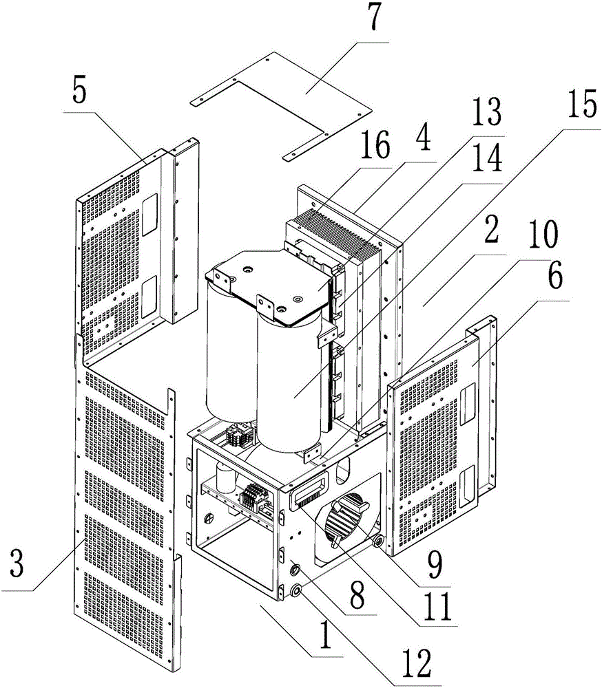
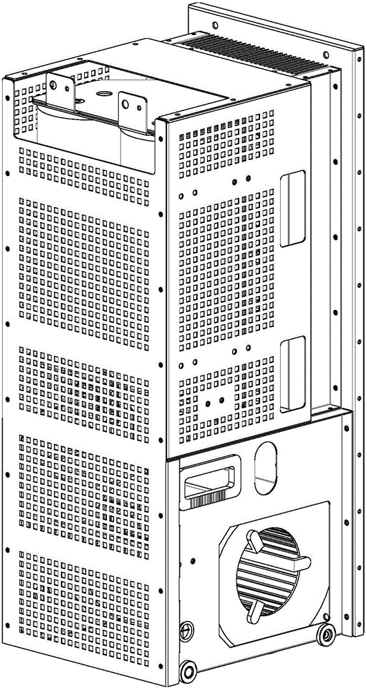
[0035] like Figures 1 to 6 As shown, a power module of a charging device includes a heat dissipation assembly 1 and a power assembly 2 , and the heat dissipation assembly 1 is disposed below the power assembly 2 and supports the power assembly 2 .

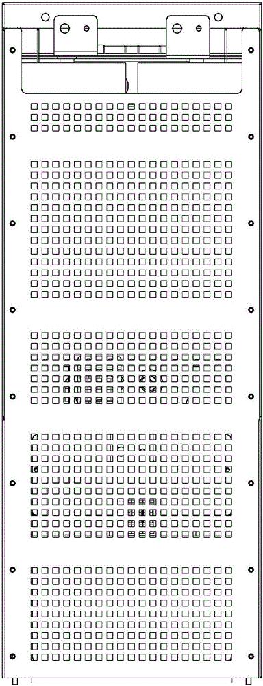
[0036] The front, rear, left, and right sides of the power assembly 2 are respectively provided with a front panel 3, a mounting plate 4, a left side panel 5, and a right side panel 6, and the left, right, and rear sides of the power assembly 2 are respectively connected to The left side plate 5 and the right side plate 6 are connected to the mounting plate 4, an upper cover plate 7 is provided above the power assembly 2, and the upper cover plate 7 is connected to the ...


PUM


Abstract

The invention relates to a charging device power module. The charging device power module comprises a heat dissipation assembly and a power assembly, wherein the heat dissipation assembly is arranged below the power assembly, and supports the power assembly; a front side, a back side, a left side and a right side of the power assembly are provided with a front panel, a mounting plate, a left side plate and a right side plate respectively; the left side, the right side and the back side of the power assembly are connected with the left side plate, the right side plate and the mounting plate respectively; an upper cover plate is arranged above the power assembly; the upper cover plate is connected with the upper ends of the mounting plate, the left side plate and the right side plate respectively; a front side and a back side of the heat dissipation assembly are connected with the front panel and the mounting plate respectively; and upper ends of a left side and a right side of the heat dissipation assembly are connected with lower ends of the left side plate and the right side plate respectively. The charging device power module has the advantages of small size, high capacity, high heat dissipation speed, low noise and high replaceability. Through adoption of a standard and integral module design, the charging device power module can be mounted and repaired conveniently and rapidly, and can be produced and assembled in batches; the production efficiency is increased effectively; and the reliable running and stability of a tramcar charging device are ensured.

Description

technical field [0001] The invention relates to the technical field of charging, in particular to a power module of a charging device. Background technique [0002] Due to the innovative design of energy storage, the new modern tram has neither exhaust pollution nor overhead power grid operation. The biggest feature of this tram is that it uses a supercapacitor as the traction power supply, and there is no need to erect aerial cables "spider webs" ", can be laid directly on existing roads, mixed with other public transportation, without wasting land resources. At the same time, ground charging devices can be installed at each station. When the train enters the station, it can use the time for passengers to get on and off the train to quickly complete the charging. It can also absorb the energy generated during braking and convert it into electrical energy for storage and reuse. The recovery efficiency is over 85%. . The new modern tram has the characteristics of safety and...

Claims


Application Information

Patent Timeline
IPC IPC(8): H02M1/00H05K7/20H05K5/02
CPCH02M1/00H05K5/0213H05K5/0217H05K5/023H05K5/0234H05K7/20145
Inventor 陈兵李蕾潘拥军何贤伟张光平龚杰戴炎熊丽王文
Owner WUHAN ZHONGZHI ELECTRIC
Learn More