
Air conditioner and control method for the air conditioner

An air-conditioning device and control device technology, applied in the direction of control input related to air characteristics, space heating and ventilation control input, air-conditioning system, etc., can solve problems such as rising relative humidity in rooms, not removing latent heat in rooms, and discomfort, etc. Achieve the effect of improving dehumidification performance, improving maintenance performance, and improving cost performance

Active Publication Date: 2019-02-15
MITSUBISHI ELECTRIC CORP
View PDF7 Cites 0 Cited by
  • Summary
  • Abstract
  • Description
  • Claims
  • Application Information

AI Technical Summary

Problems solved by technology

At this time, the evaporation temperature in the evaporator rises, and the sensible heat of the room, etc. is removed, but the latent heat of the room, etc. is not removed, and the relative humidity of the room, etc. rises, and people in the air-conditioned space feel uncomfortable

Method used


Image

  • Air conditioner and control method for the air conditioner
  • Air conditioner and control method for the air conditioner
  • Air conditioner and control method for the air conditioner

Examples


Embodiment approach 1

[0028] The air conditioner of Embodiment 1 will be described.

[0029]

[0030] Hereinafter, the configuration of the air conditioner according to Embodiment 1 will be described.

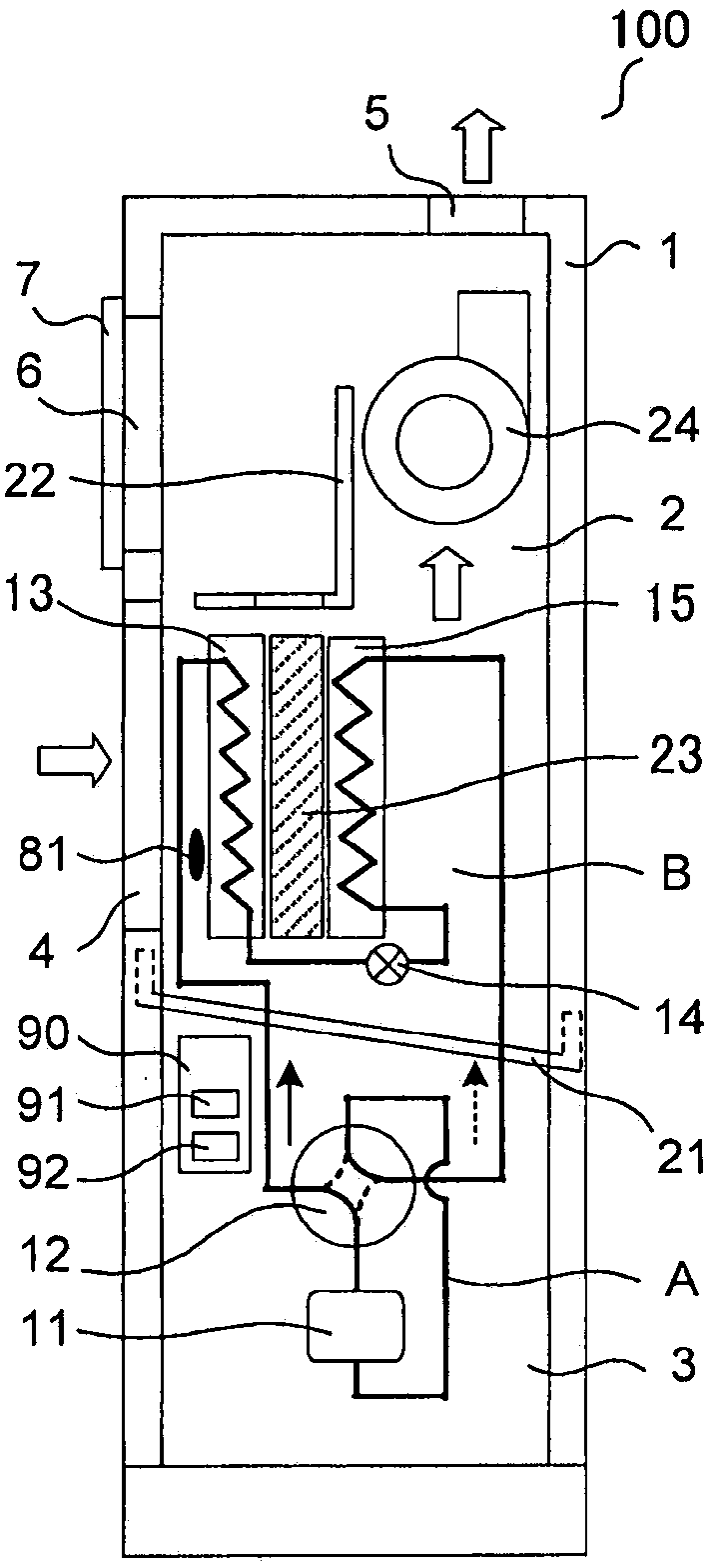
[0031] figure 1 It is a figure for demonstrating the structure of the air-conditioning apparatus of Embodiment 1. In addition, in figure 1 In , the flow of air is indicated by white arrows, the flow of refrigerant in the first operation mode is indicated by solid arrows, and the flow of refrigerant in the second operation mode is indicated by dotted arrows. In addition, the flow path of the four-way valve 12 in the first operation mode is indicated by a solid line, and the flow path of the four-way valve 12 in the second operation mode is indicated by a broken line.

[0032] like figure 1 As shown, the air conditioner 100 includes a compressor 11, a four-way valve 12 as a flow path switching device, a first heat exchanger 13, an expansion valve 14 as a decompression device, and a first heat...

Embodiment approach 2

[0088] An air conditioner according to Embodiment 2 will be described.

[0089] In addition, descriptions that overlap or are similar to Embodiment 1 are appropriately simplified or omitted.

[0090]

[0091] Hereinafter, the dehumidification operation of the air conditioner according to Embodiment 2 will be described.

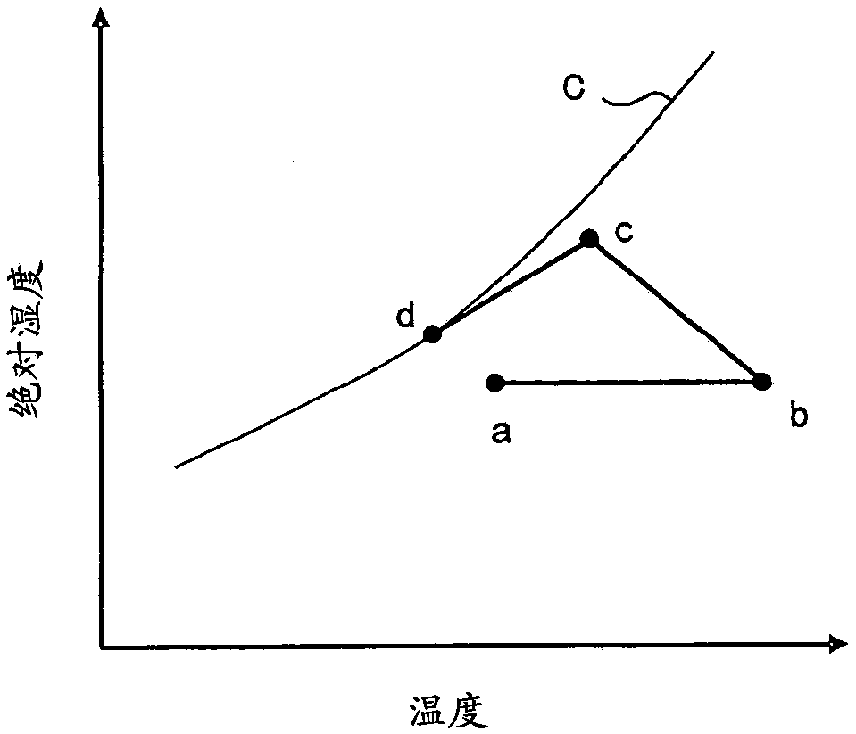
[0092] In the air conditioner 100, when switching to the second operation mode or when the second operation mode is executed, the temperature determination unit 91 of the control device 90 determines whether the temperature of the intake air is a preset value based on the detection signal of the temperature and humidity sensor 81. below the base temperature. Then, when the temperature determination unit 91 of the control device 90 determines that the temperature of the intake air is equal to or lower than the preset reference temperature, immediately thereafter or after the elapse of the set standby time, the third control unit 90 Operation mode setting un...


PUM


Abstract

The air conditioner (100) has: a refrigerant circulation circuit (A); a desiccant material arranged between the first heat exchanger (13) and the second heat exchanger (15); 13), desiccant material, the air-supply device of the airflow that the order of the second heat exchanger (15) passes through; The temperature detection mechanism that detects the temperature of airflow; A control device (90) for switching between the first operation mode of desorption and the second operation mode of adsorbing moisture to the desiccant material, and the control device (90) has a temperature determination function for determining whether the temperature of the airflow detected by the temperature detection mechanism is low or high mechanism, and a third operation mode setting mechanism that transitions to a third operation mode when the temperature judging mechanism determines that the temperature of the airflow is low. In the third operation mode, the surface temperature of the first heat exchanger (13) The desiccant material absorbs moisture in a state higher than the surface temperature of the first heat exchanger (13) in the second operation mode.

Description

technical field [0001] The invention relates to an air conditioner with dehumidification function and a control method for the air conditioner with dehumidification function. Background technique [0002] As a conventional air conditioner, for example, there is an air conditioner provided with a refrigerant circulation circuit that sequentially connects a compressor, a condenser, an expansion valve, and an evaporator with piping, and a defrosting heater. In the refrigerant circulation circuit, the refrigerant compressed by the compressor becomes high-temperature and high-pressure gas refrigerant and is sent to the condenser. The refrigerant flowing into the condenser liquefies by giving off heat to the air. The liquefied refrigerant is decompressed by the expansion valve, becomes a gas-liquid two-phase refrigerant, and flows into the evaporator. The gas-liquid two-phase refrigerant vaporizes by absorbing heat from the surrounding air in the evaporator, and is sucked into t...

Claims


Application Information

Patent Timeline
Patent Type & Authority Patents(China)
IPC IPC(8): F24F3/14F24F1/0358F24F11/89F24F1/0323
CPCF24F3/14F24F13/22F24F3/1411F24F11/30F24F2110/10F24F1/0323F24F1/0358F24F11/77F24F11/84F24F11/63F24F11/41
Inventor 杉本猛伊藤慎一冈岛圭吾田中学
Owner MITSUBISHI ELECTRIC CORP
Learn More