
Plastic film winding device

A winding device and technology of plastic film, applied in the field of plastic manufacturing, can solve the problems of insufficient density of film roll, easy to stretch, easy to be torn, etc.

Inactive Publication Date: 2016-09-21
重庆敏驰塑胶有限公司
View PDF0 Cites 5 Cited by
  • Summary
  • Abstract
  • Description
  • Claims
  • Application Information

AI Technical Summary

Problems solved by technology

In the production process of plastic film, the plastic film after calendering needs to be rewound by the winding mechanism. When rewinding the plastic film, in order to prevent the film from wrinkling, it is often necessary to tension the film to ensure that the film is flat; The existing winding device usually stretches the film through the flattening roller and the feeding roller. The flattening roller is a driven roller, and the feeding roller is a driving roller. The feeding roller pulls the film to move by friction, and the film moves by friction. The force is the rotation of the flattening roller, so as to realize the tension of the film; but because the film has good ductility, it is easy to stretch after being stressed, and it is easy to be torn when the force is too large, so the surface of the flattening roller and the feeding roller are different from each other The friction force of the film should not be too large, so it often happens that the film cannot be tensioned, so that when the film is rolled up, the film is prone to wrinkles, or the film roll is not dense enough
[0003] In addition, since the diameter of the film roll will gradually increase when the film is wound, the film winding speed will gradually become faster, so that the moving speed of the film and the friction between the film and each roller will change, that is, the tension of the film hard to control

Method used


Image

  • Plastic film winding device
  • Plastic film winding device
  • Plastic film winding device

Examples


Embodiment Construction

[0017] The present invention will be described in further detail below by means of specific embodiments:

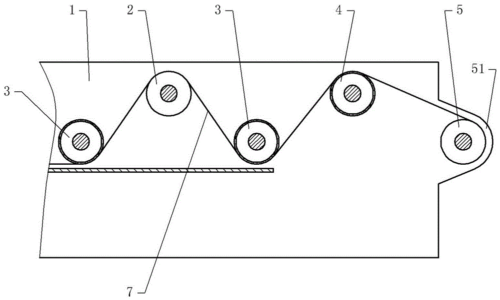
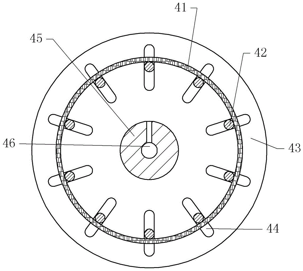
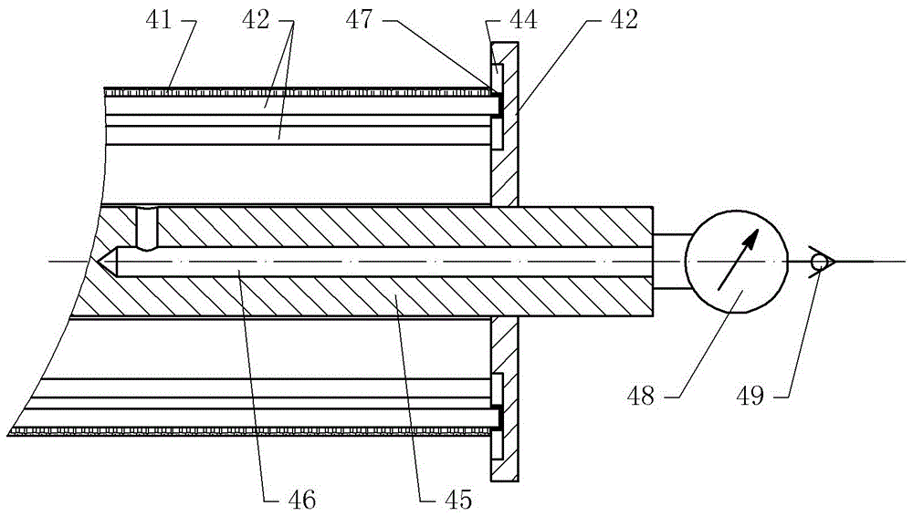
[0018] The reference signs in the drawings of the specification include: bracket 1, feeding roller 2, flattening roller 3, tension roller 4, output roller 5, film 7, rubber layer 41, steel strip 42, end cap 43, strip groove 44, roller shaft 45, air hole 46, sealing ring 47, pressure gauge 48, pressure relief valve 49.

[0019] The embodiment is basically as figure 1 Shown:

[0020] The plastic film 7 winding device of the present embodiment comprises support 1, and the feed roller 2 that is connected on the support 1, flattening roller 3 and delivery roller 5 are rotated, and the drive motor that drives feed delivery roller 2 and delivery roller 5 rotations; Drive motor and The speed reducer is connected, and the speed reducer is connected with the feeding roller 2 and the output roller 5 respectively through the chain, and the rotating speed of the output roller 5 is 2...


PUM


Abstract

The invention discloses a plastic film winding device and relates to the field of plastic manufacture. The plastic film winding device comprises a support, a feed roller, spreading rollers, a discharge roller, and a driving motor that drives the feed roller and the discharge roller to rotate. The feed roller is located between and higher than the spreading rollers that are disposed at a right side of the support. The feed roller rotates faster than the discharge roller. A tensioning roller is disposed between and slightly higher than one spreading roller and the discharge roller. The tensioning roller comprises a roller body, a roller shaft, and end caps fixed to two ends of the roller shaft. The roller body defines an air chamber, and comprises a rubber layer and steel bars fixed thereto. A plurality of bar-shaped grooves are radially formed in each end cap. Ends of the steel bars are embedded in the corresponding bar-shaped grooves. An air hole communicating with the air chamber is formed in the roller shaft, and an air connector is disposed at an end of the roller shaft. The tensioning roller provided in the plastic film winding device has a flexible body, i.e., is capable of deforming under pressure produced by a film; thus, the tension of the film can be controlled within a reasonable range.

Description

technical field [0001] The invention relates to the field of plastic manufacturing, in particular to a plastic film winding device. Background technique [0002] Plastic film is mainly made of polyvinyl chloride, polyethylene, polypropylene, polystyrene and other resins, used for packaging, and as a film layer. Plastic packaging and plastic packaging products account for an increasing share in the market, especially composite plastic flexible packaging, which has been widely used in food, medicine, chemical and other fields, among which food packaging accounts for the largest proportion, such as beverage packaging , quick-frozen food packaging, cooking food packaging, fast food packaging, etc., these products have brought great convenience to people's lives. In the production process of plastic film, the plastic film after calendering needs to be rewound by the winding mechanism. When rewinding the plastic film, in order to prevent the film from wrinkling, it is often neces...

Claims


Application Information

Patent Timeline
IPC IPC(8): B65H20/02B65H23/34B65H23/26B65H27/00
CPCB65H20/02B65H23/26B65H23/34B65H27/00B65H2404/1351B65H2601/25
Inventor 杨治焱
Owner 重庆敏驰塑胶有限公司
Learn More