Box type evaporator for waste heat utilization of high-temperature solid materials

A high-temperature solid and evaporator technology, which is applied in the field of high-temperature solid material waste heat utilization box-type evaporators, can solve the problems of inability to produce steam, ineffective utilization of waste heat, and inability to use soda-water mixture, etc., and achieves improved utilization of waste heat, compact structure, The effect of increasing the volume

Active Publication Date: 2016-09-21
SHANDONG LIANXING ENERGY SAVING SERVICE
View PDF5 Cites 2 Cited by
  • Summary
  • Abstract
  • Description
  • Claims
  • Application Information

AI Technical Summary

Problems solved by technology

Patent application document CN201510153898.0 discloses a large-scale box-type high-temperature material heat exchanger. The large-scale box-type high-temperature material heat exchanger exchanges heat for high-temperature materials through a water-cooled box cover and a heat-exchange box. The tank cover and the wall of the heat exchange box are of a sandwich structure, which is a non-pressure-bearing type. Therefore, the cover of the cold water exchange tank and the heat exchange tank can only flow water, not the mixture of steam and water, so that hot water can only be produced by using the waste heat of high-temperature materials , unable to produce steam, waste heat cannot be efficiently utilized

Method used


Image

  • Box type evaporator for waste heat utilization of high-temperature solid materials
  • Box type evaporator for waste heat utilization of high-temperature solid materials
  • Box type evaporator for waste heat utilization of high-temperature solid materials

Examples


Embodiment 1

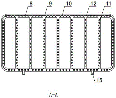
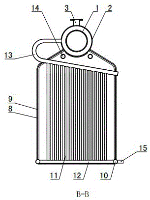
[0032] Such as figure 1 As shown: the length of the outer cylinder 2 is less than the length of the inner cylinder 1, and the inner diameter of the outer cylinder 2 is greater than the outer diameter of the inner cylinder 1, and the two ends of the outer cylinder 2 are provided with annular cover plates, and the outer edge of the annular cover plate and the outer The pipe wall of the cylinder 2 is welded and sealed, and the inner edge is welded and sealed with the outer wall of the inner cylinder 1, thereby forming a sleeve type header between the outer cylinder 2 and the inner cylinder 1. The feed port 4 is arranged at the right end of the sleeve header, and the feed port 4 communicates with the inner cavity of the inner cylinder 1 . A water outlet 3 is arranged in the middle of the sleeve-type header, and the water outlet 3 is arranged on the upper part of the sleeve-type header, and the water outlet 3 communicates with the inner cavity of the outer cylinder 2 .

[0033] Th...

Embodiment 2

[0047] Such as Figure 5~6 As shown: the difference between Embodiment 2 and Embodiment 1 is that the manifold 13 is arranged horizontally, both ends of the manifold 13 are closed, and the upper end of the inner heat exchange tube 11 communicates with the manifold 13 . A connecting pipe 16 is arranged between the collecting pipe 13 and the outer cylinder 2. The connecting pipe 16 is arranged vertically.

Embodiment 3

[0049] Such as Figure 7 As shown: the difference between embodiment 3 and embodiment 1 is that the confluence pipe 13 includes two horizontal parts and a bent part below, and the two horizontal parts are symmetrically arranged on both sides of the outer cylinder 2, and the two horizontal parts are close to the outer cylinder 2 One end communicates with the inner cavity of the outer cylinder 2, and the ends of the two horizontal parts away from the outer cylinder 2 respectively communicate with the two ends of the bending part. The folds are connected.

[0050] The feeding port 4 is arranged in the middle part of the inner cylinder 1, and the helical blades of the water-cooled spiral body are separated from the middle part, and the helical blades on both sides of the middle part are opposite in direction of rotation. When the water-cooled spiral rotates, it pushes the material toward both ends.


PUM


Abstract

The invention discloses a box type evaporator for waste heat utilization of high-temperature solid materials and belongs to the field of cooling equipment for the high-temperature solid materials. The box type evaporator is characterized in that an outer cylinderl (2) and an inner cylinder (1) are combined to form a sleeve type header; the lower end of a heat exchange box (7) is open; the sleeve type header seals the upper end of the heat exchange box (7); a feeding port (4) communicated with the inner cylinder (1) is arranged at the upper part of the sleeve type header; a water-cooled spiral distributor for conveying and cooling the materials is arranged inside the inner cylinder (1); a heat exchange cavity is arranged on the side wall of the heat exchange box (7) ad is communicated with an inner cavity of the outer cylinder (2); multiple isolating mechanisms are arranged inside the heat exchange box (7) in parallel and divide the heat exchange box (7) into multiple material channels; and the materials in the inner cylinder (1) fall into the material channels via discharge ports (6). Both the sleeve type header and the heat exchange box of the box type evaporator for waste heat utilization of the high-temperature solid materials can bear pressure, so that the evaporator can be directly applied to production of steam, and waste heat of the high-temperature materials is efficiently utilized.

Description

technical field [0001] A box-type evaporator for utilizing waste heat of high-temperature solid materials belongs to the field of cooling equipment for high-temperature solid materials. Background technique [0002] In industrial production, there are many high-temperature solid materials with high temperature, such as ash discharged from circulating fluidized bed, calcined coke formed by calcination of petroleum coke, semi-coke produced by dry distillation, powder coke formed by pyrolysis of pulverized coal, etc., they carry Waste heat can be recycled. Especially for the seed material produced by rotary kiln dry distillation, powdered semi-coke, and powdered coke formed by pyrolysis of pulverized coal, the output coke of a single set of equipment is large, and the remaining heat has more utilization value. Patent application document CN201510153898.0 discloses a large-scale box-type high-temperature material heat exchanger. The large-scale box-type high-temperature materia...

Claims


Application Information

Patent Timeline
Patent Type & Authority Applications(China)
IPC IPC(8): F22B1/04F22G1/00
CPCF22B1/04F22G1/00Y02P80/10
Inventor 刘永启
Owner SHANDONG LIANXING ENERGY SAVING SERVICE
Why Eureka
Try Eureka