
Self-detection indirect heating type rotary furnace

A heating type, rotary furnace technology, applied in the field of heating rotary furnace, bulk material drying, can solve the problems of uneven heating of the furnace barrel, uneven heating, contaminated materials, etc., to achieve uniform heating and stable operation, continuous and stable temperature, The effect of easy maintenance operation

Active Publication Date: 2016-09-21
HUNAN CHANGZHONG MACHINERY
View PDF5 Cites 1 Cited by
  • Summary
  • Abstract
  • Description
  • Claims
  • Application Information

AI Technical Summary

Problems solved by technology

[0003] The internal heating type rotary furnace heats the material by entering the heat source into the furnace barrel. Generally, the fuel enters the furnace barrel for combustion and the high-temperature flue gas after combustion enters the furnace barrel for heating. The heating medium directly contacts the material, which will pollute the material and make the subsequent treatment process of the material Increased difficulty, such as using coal as fuel will increase the ash content of the material
In addition, the flue gas directly scours the material, which may affect the chemical reaction in the heating process.
[0004] Although the existing external heating type rotary furnace overcomes the above-mentioned shortcomings of the internal heating type rotary furnace, the existing external heating type rotary furnace is directly fired and heated in the heating furnace, and there is still the situation that the furnace tube is heated unevenly, which reduces the impact on the rotary furnace. Thermal efficiency, and the combustion process is difficult to control, which may lead to waste of energy due to insufficient combustion, and the emission of carbon monoxide into the atmosphere will also pollute the environment
[0005] The rotary furnace adopts the electric heating element, that is, the resistance wire heating method, and the resistance wire is arranged on the bottom and side of the heating furnace. When the resistance wire is damaged, it needs to be cooled and stopped before it can be replaced. After the replacement, it needs to be heated again, which is a waste of time and energy. , inconvenient maintenance, reducing production efficiency
Moreover, in the prior art, the heating method of the rotary kiln is single, which will affect the production when the heat source is limited or the heat source is not stable, causing the production line to stop working, which will seriously affect the production efficiency.
At the same time, once there is a problem or uneven heating in the existing technology, manual inspection and maintenance are required, which is extremely inconvenient, and it cannot automatically arrange the rapid heating of the furnace locally to achieve uniform heating as a whole

Method used


Image

  • Self-detection indirect heating type rotary furnace
  • Self-detection indirect heating type rotary furnace
  • Self-detection indirect heating type rotary furnace

Examples


specific Embodiment 1

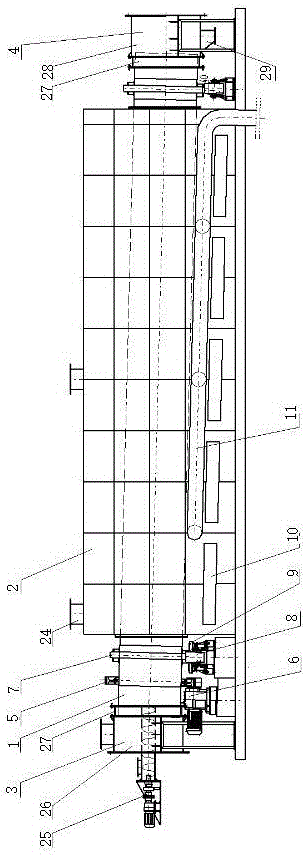
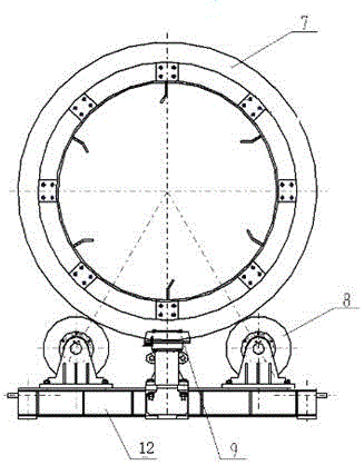
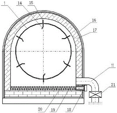
[0031] A self-inspecting indirect heating rotary furnace, comprising a furnace drum 1, a heating furnace 2, a feeding system 3, a discharging system 4, a drive system, and an electrical control system, characterized in that the heating furnace 2 is located in the middle of the furnace 1 One end of the furnace drum 1 is connected to the feeding system 3, and the other end is connected to the discharging system 4. The feeding system 3 transports the material to the heating furnace 2 through the feeding screw conveyor 25, and the driving system provides the transportation force to heat the furnace 2. Electric heating elements are evenly arranged at the bottom, and a hot air system 11 is arranged in the heating furnace 2 through bent pipes. A temperature control detector is installed inside the heating furnace 2, and the heating and heating are intelligently controlled through the electrical control system. After the material is heated, it passes through the The discharge system 4 ...

specific Embodiment 2

[0043] A self-inspecting indirect heating rotary furnace, comprising a furnace drum 1, a heating furnace 2, a feeding system 3, a discharging system 4, a drive system, and an electrical control system, characterized in that the heating furnace 2 is located in the middle of the furnace 1 One end of the furnace drum 1 is connected to the feeding system 3, and the other end is connected to the discharging system 4. The feeding system 3 transports the material to the heating furnace 2 through the feeding screw conveyor 25, and the driving system provides the transportation force to heat the furnace 2. Electric heating elements are evenly arranged at the bottom, and a hot air system 11 is arranged in the heating furnace 2 through bent pipes. A temperature control detector is installed inside the heating furnace 2, and the heating and heating are intelligently controlled through the electrical control system. After the material is heated, it passes through the The discharge system 4 ...


PUM


Abstract

The invention relates to a self-detection indirect heating type rotary furnace. The rotary furnace comprises a furnace tube, a heating hearth, a feeding system, a discharging system, a drive system and an electrical control system and is characterized in that the heating hearth is located in the middle inside the furnace tube, one end of the furnace tube is connected with the feeding system, the other end of the furnace tube is connected with the discharging system, the feeding system conveys materials to the heating furnace through a feeding spiral conveying mechanism, and transportation force is provided through the drive system; electric heating elements are evenly arranged at the bottom of the heating furnace, a hot air system is further arranged in the heating furnace through a bending type pipeline, a temperature control detection instrument is arranged inside the heating furnace, heating and heat supply are controlled through the electrical control system, and after being heated, the materials are discharged through the discharging system; and according to the rotary furnace, under the isolation state, the materials are indirectly dried and heated, heat treatment performance is good, production efficiency is high, the service life is long, the beneficial effects of being high in production capacity, high in mechanization degree and easy to maintain and operate are achieved, and the requirements of energy saving and environment friendliness are met.

Description

technical field [0001] The invention relates to a rotary kiln for drying and heating bulk materials, in particular to an indirect heating rotary kiln through electric heating elements or high-temperature flue gas. Background technique [0002] The rotary kiln is mainly used for drying and heating treatment of solid granular and powdery materials. The rotary kiln type is usually divided into two types: external heating type and internal heating type. [0003] The internal heating type rotary furnace heats the material by entering the heat source into the furnace barrel. Generally, the fuel enters the furnace barrel for combustion and the high-temperature flue gas after combustion enters the furnace barrel for heating. The heating medium directly contacts the material, which will pollute the material and make the subsequent treatment process of the material Increased difficulty, such as using coal as fuel will increase the ash content of the material. In addition, the flue ga...

Claims


Application Information

Patent Timeline
IPC IPC(8): F27B7/10F27B7/14F27B7/34
CPCF27B7/10F27B7/14F27B7/34
Inventor 文向前吴海燕曾文凤
Owner HUNAN CHANGZHONG MACHINERY
Learn More