High-voltage alternating-current circuit breaker arc burning time measuring system and method

A high-voltage AC and arcing time technology, applied in the field of power system power transmission, transformation and distribution, can solve the problems of measurement system measurement, inability to measure arcing time of high-voltage AC circuit breaker breaking test, inability to identify jump characteristic points, etc.

Active Publication Date: 2016-09-21
STATE GRID ZHEJIANG ELECTRIC POWER CO LTD SHAOXING POWER SUPPLY CO +2
View PDF9 Cites 20 Cited by
  • Summary
  • Abstract
  • Description
  • Claims
  • Application Information

AI Technical Summary

Problems solved by technology

[0012] However, for the breaking test of AC high-voltage switchgear, the arcing time is difficult to be measured by the conventional measurement system
Taking the 10kV AC high-voltage vacuum circuit breaker breaking capacitor bank current test as an example, the range of the high-voltage divider measurement system is set according to the expected maximum transient recovery voltage that may occur in the operation overvoltage. The typical value of the range reaches 100kV, and the accuracy of the voltage divider is typical The value is 0.5%, and the fracture recovery voltage obtained by differential can reach 1% (2*0.5%) only by the ratio error of the voltage divider, that is, the system error caused by the ratio alone may be as high as 1000V, including zero drift, electronic Digital noise, voltage drop error caused by lead wire impedance, etc. In theory, there will be an interference level of at least several hundred volts in the closing stage when the recovery voltage is zero, while the arc voltage in the arcing stage is only about 20 volts, and the recovery voltage is medium The arc voltage component is completely submerged by the interference level as high as dozens of times, and it is impossible to distinguish the characteristic point of the jump, so the conventional measurement system and method cannot measure the arcing time of the breaking test of the high-voltage AC circuit breaker

Method used


Image

  • High-voltage alternating-current circuit breaker arc burning time measuring system and method
  • High-voltage alternating-current circuit breaker arc burning time measuring system and method
  • High-voltage alternating-current circuit breaker arc burning time measuring system and method

Examples


Embodiment Construction

[0065] In this embodiment 1, the arcing time is determined by the current switching test of the AC high-voltage vacuum circuit breaker 400A back-to-back switching capacitor bank conducted by the quality inspection and testing center of the complete set of reactive power compensation equipment in the electric power industry.

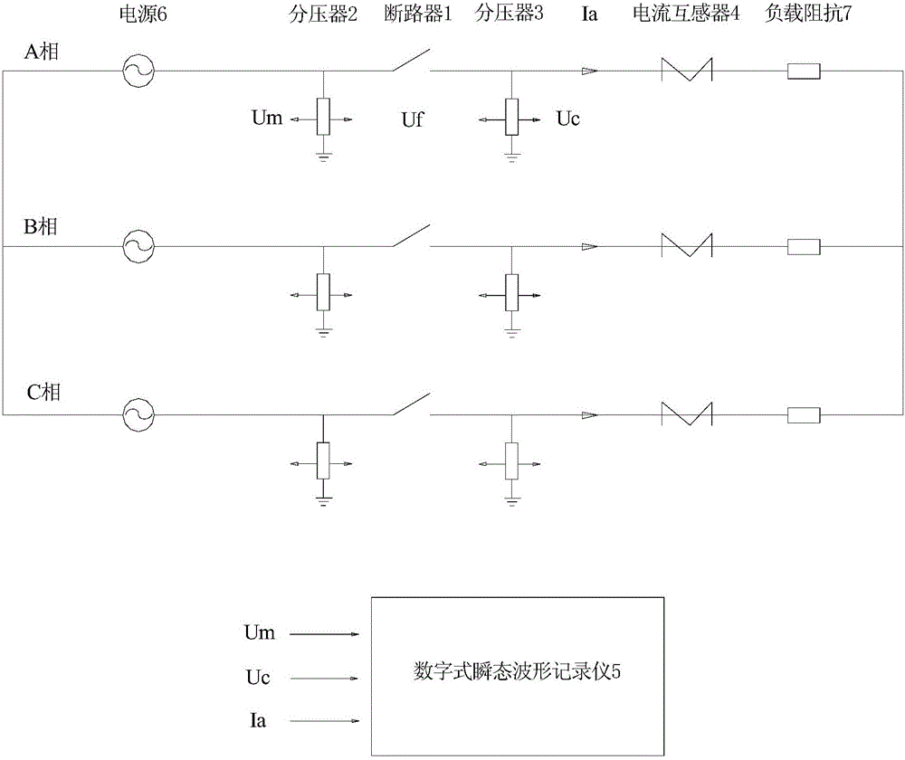
[0066] This embodiment provides a high-voltage AC circuit breaker arcing time measurement system, the schematic diagram of the test circuit is as follows figure 1 As shown, the test product includes a high-voltage AC circuit breaker 1, the bus side (power side) of the high-voltage AC circuit breaker is installed with a bus-side voltage divider 2 to the ground, and the load side of the high-voltage AC circuit breaker is installed with a load-side divider to the ground. A voltage transformer 3, the high-voltage AC circuit breaker 1 is installed in series with a current transformer 4, the bus side voltage divider 2, the load side voltage divider 3, the secon...


PUM


Abstract

The invention discloses a high-voltage alternating-current circuit breaker arc burning time measuring system and method. A measuring collection system composed of a voltage divider, a current transformer, a transient waveform recorder and the like is utilized, post optimization processing is carried out on the waveform data through data analysis software, the error interference level caused by a ratio error, a zero drift and electronic digital noise is eliminated or substantially reduced, and the distinguishability of an arc voltage component of only tens of volts is substantially improved; in addition, the step characteristic of the arc voltage component before and after arc burning is utilized, starting and ending moments of the jumping of the arc voltage component are calibrated on a voltage waveform, and the purpose of precisely measuring the arc burning time is realized.

Description

technical field [0001] The invention relates to a system and method for measuring arcing time of a high-voltage AC circuit breaker, belonging to the technical field of power transmission, transformation and distribution of power systems. Background technique [0002] The arcing time is from the moment when the AC high-voltage switchgear breaks the current from the moment when the contact of the circuit breaker is just divided to the moment when the current crosses zero and the arc is stopped. At this stage, the current exists in the form of an arc in the switch arc extinguishing chamber. Most of the high-voltage AC circuit breaker breaking tests required by the 1984-2014 "High Voltage AC Circuit Breaker" standard require the breaking test to be carried out at the required intervals between the longest and the shortest arcing time, and between the longest and the shortest arcing time. Taking the current breaking test requirements of phase capacitor banks as an example, the re...

Claims


Application Information

Patent Timeline
Patent Type & Authority Applications(China)
IPC IPC(8): G01R31/327G01R31/333
CPCG01R31/3272G01R31/3333
Inventor 金百荣蔡重凯李电陈晓宇洪金琪秋勇吕丹沈勇施明明夏嵘严军王国栋
Owner STATE GRID ZHEJIANG ELECTRIC POWER CO LTD SHAOXING POWER SUPPLY CO
Why Eureka
Try Eureka