Photovoltaic panel adjustment apparatus and photovoltaic energy conversion apparatus
A photovoltaic panel and adjusting device technology, applied in the photovoltaic field, can solve the problems such as the difficulty of freely changing the angle of the photovoltaic panel and the inability to fully utilize the photovoltaic panel, and achieve the effects of high degree of automation, simple structure and convenient operation.
- Summary
- Abstract
- Description
- Claims
- Application Information
AI Technical Summary
Problems solved by technology
Method used
Image
Examples
no. 1 example
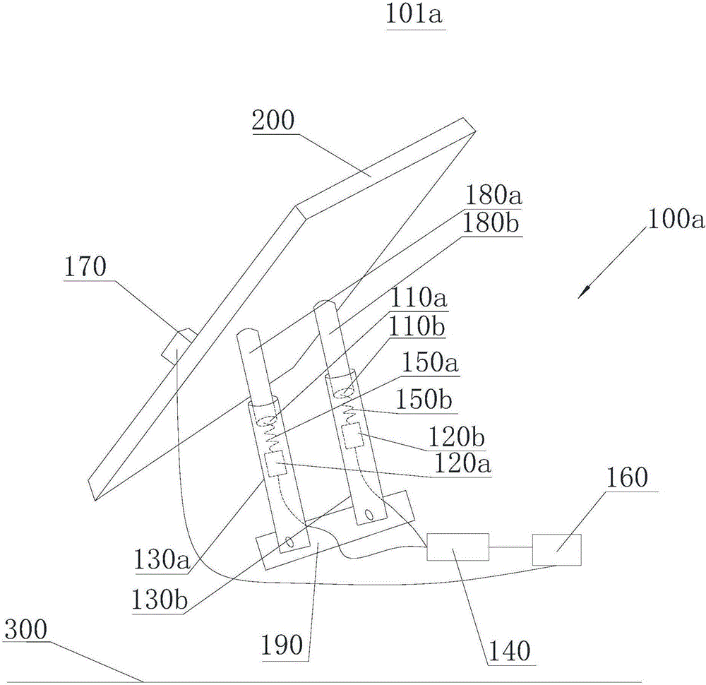
[0028] See attached figure 1 A photovoltaic conversion device 101a provided by the first embodiment of the present invention includes a photovoltaic panel adjustment device 100a and a photovoltaic panel 200, and the photovoltaic panel adjustment device 100a includes a first permanent magnet 110a, a first electromagnet 120a, a first guide support 130a. Driving the control circuit 140 .
[0029] Photovoltaic panel 200 is the main device for absorbing and converting solar energy. It is usually installed at an inclination. One end of photovoltaic panel 200 is rotatably connected to ground 300, so that photovoltaic panel 200 can rotate relative to ground 300 to achieve the purpose of adjusting the angle. A support frame (not shown) is provided below the photovoltaic panel 200, and the support frame can support the photovoltaic panel 200 so that the photovoltaic panel 200 is always in a tilted state so as to better receive sunlight radiation. Certainly, in other embodiments, the ph...
no. 2 example
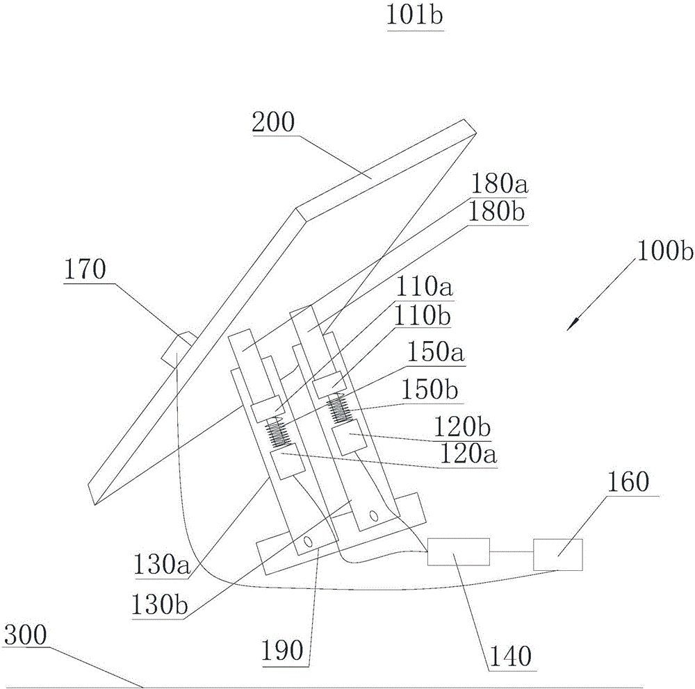
[0046] See attached figure 2 , The photovoltaic energy conversion device 101b provided in the second embodiment of the present invention includes a photovoltaic panel adjustment device 100b and a photovoltaic panel, and the photovoltaic panel adjustment device 100b also includes a first permanent magnet 110a, a second permanent magnet 110b, and a first electromagnet 120a , the second electromagnet 120b, the first guide support 130a, the second guide support 130b and the drive control circuit 140. For the connection manner and positional relationship between the above components, refer to the first embodiment.
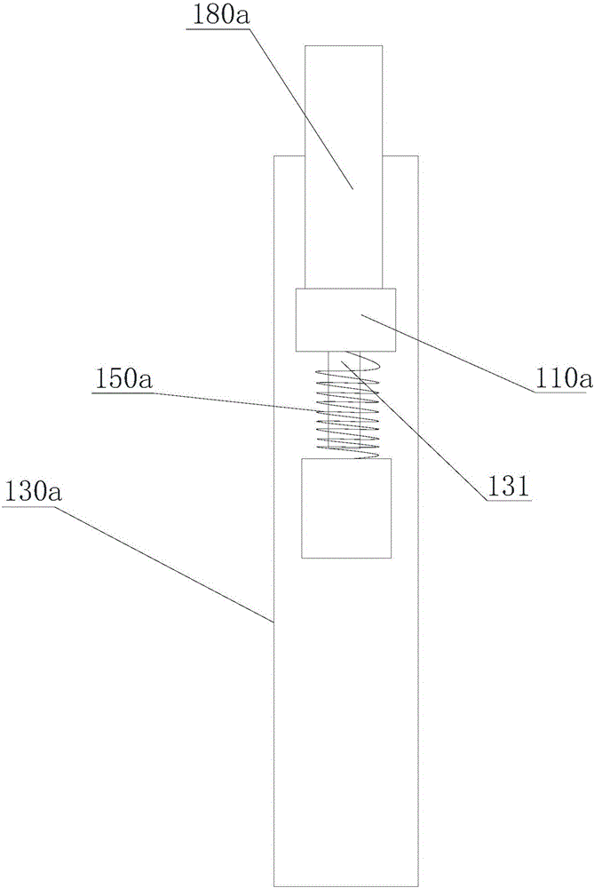
[0047] In this example, see the attached figure 2 , the shapes and structures of the first guide support 130a and the first sliding connector 180a are different from the first embodiment, the first guide support 130a is a solid body, and the surface of the first guide support 130a is provided with the first sliding connector 180a Cooperating with the chute 131, the ...
PUM
 Abstract
Description
Claims
Application Information
 - R&D
- Intellectual Property
- Life Sciences
- Materials
- Tech Scout
- Unparalleled Data Quality
- Higher Quality Content
- 60% Fewer Hallucinations
Browse by: Latest US Patents, China's latest patents, Technical Efficacy Thesaurus, Application Domain, Technology Topic, Popular Technical Reports.
© 2025 PatSnap. All rights reserved.Legal|Privacy policy|Modern Slavery Act Transparency Statement|Sitemap|About US| Contact US: help@patsnap.com


