Passive optical interconnection network structure based on software definition and data communication method

A software-defined and network-structured technology, applied in the field of communication, can solve problems such as large packet delay, network time extension, and poor scalability, and achieve the effects of small packet end-to-end delay, improved reliability, and improved throughput

Inactive Publication Date: 2016-09-21
CHONGQING UNIV
View PDF5 Cites 10 Cited by
  • Summary
  • Abstract
  • Description
  • Claims
  • Application Information

AI Technical Summary

Problems solved by technology

There are many defects in this kind of network: 1) the equal bandwidth is small, and the network throughput is limited by the network topology and the capacity of the root node Ethernet switch; Bottlenecks limit the scalability of the network; 3) High energy consumption, the access layer, aggregation layer and core layer use a large number of electrical Ethernet switches, which consume a lot of energy and energy consumption is a key issue that data center operators cannot ignore
This type of optical interconnection network structure has some disadvantages: 1) The packet delay is large, and the optical circuit switch is used in the optical switching, that is, the switch based on the micro-electromechanical system (MEMS). When the traffic matrix changes, the weight of the optical circuit switch The construction process is very time-consuming, usually tens of milliseconds, resulting in a relatively long network delay
2) The energy consumption of the network is high, and there are still some electric packet switches in the photoelectric hybrid network architecture, and the packets need to undergo photoelectric-electrical-optical conversion, which consumes a lot of energy and increases the energy consumption of the network
However, the POXN architecture also has some shortcomings: 1) The distributed access control protocol will lead to frequent exchange of control information between servers, while the data and control information of the POXN architecture share optical link resources, thus increasing the complexity of the control plane ; 2) HEDA is a distributed access control protocol, which needs to be synchronized between the servers in the rack. Since the distance between the servers in the same rack is relatively short, synchronization will pose a high challenge to the control plane of the network. Require
This process will lead to a large end-to-end delay of the packet, which is difficult to meet the real-time requirements of some applications (such as cloud computing applications)

Method used


Image

  • Passive optical interconnection network structure based on software definition and data communication method
  • Passive optical interconnection network structure based on software definition and data communication method
  • Passive optical interconnection network structure based on software definition and data communication method

Examples


Embodiment Construction

[0035] The preferred embodiments of the present invention will be described in detail below in conjunction with the accompanying drawings; it should be understood that the preferred embodiments are only for illustrating the present invention, rather than limiting the protection scope of the present invention.

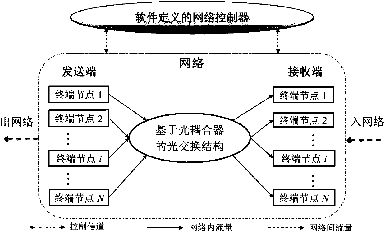
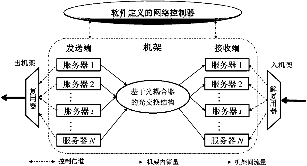
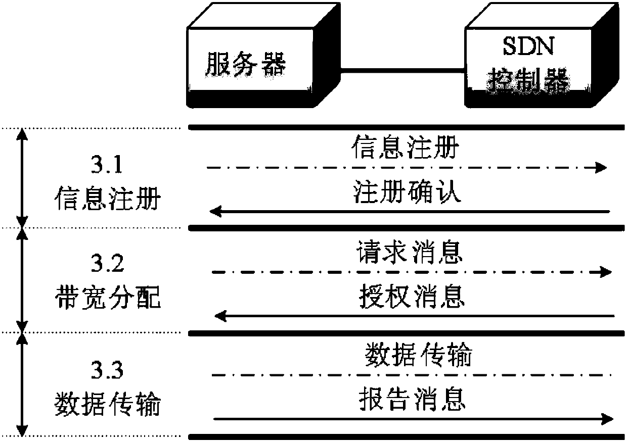
[0036] A software-defined passive optical interconnection network structure (SD-POIN, Software Defined Passive Optical Interconnection Networks), including terminal nodes, an optocoupler-based switching structure and a software-defined network controller, an optocoupler-based switch The structural interconnection of terminal nodes constitutes an optical data channel; the software-defined network controller connects each terminal node to form an electrical control channel, and the software-defined network controller collects network status information and dynamically allocates network resources for terminal nodes.

[0037] The terminal node needs to be equipped with a lig...


PUM


Abstract

The invention discloses a passive optical interconnection network structure based on software definition. The structure comprises terminal nodes, a switching structure based on an optical coupler and a software defined network controller. The switching structure based on the optical coupler is interconnected with the terminal nodes, thereby forming an optical data channel. The software defined network controller is connected with each terminal node, thereby forming an electric control channel. The software defined network controller collects network state information and allocates network resources to the terminal nodes dynamically. The network controller coordinates communication among the nodes through adoption of a software defined medium access control SD-MAC mechanism, collisions occurring in the network are avoided, and the network throughput is improved. According to the SD-MAC mechanism, the bandwidth resources are allocated to the terminal nodes through adoption of a maximum-minimum fair shared bandwidth allocation algorithm, and the fair and order data communication among the terminal nodes is realized.

Description

technical field [0001] The invention relates to the field of communication technology, in particular to a software-defined passive optical internet structure and a data communication method. Background technique [0002] Optical networks have the advantages of high bandwidth and low latency, and are widely used in scenarios such as backbone networks, access networks, and data center networks. Taking a data center network as an example, a traditional data center network (DCN, Data Center Network) adopts a layered tree topology and uses an electrical Ethernet switch as a switching node. There are many defects in this kind of network: 1) the equal bandwidth is small, and the network throughput is limited by the network topology and the capacity of the root node Ethernet switch; Bottlenecks limit the scalability of the network; 3) High energy consumption. The access layer, aggregation layer, and core layer use a large number of electrical Ethernet switches, which consume a lot ...

Claims


Application Information

Patent Timeline
Patent Type & Authority Applications(China)
IPC IPC(8): H04L12/24H04Q11/00H04B10/25
CPCH04B10/2589H04L41/0896H04Q11/0005H04Q11/0067H04Q2011/0086H04Q2011/009
Inventor 蔡岳平罗森周丽
Owner CHONGQING UNIV
Why Eureka
Try Eureka