Fixing device for loop laying tube of loop laying head

A technology of fixing device and laying tube, which is applied in the field of laying machine equipment, can solve the problems of large vibration of laying machine and weight change of pipe clamp, etc., and achieve the effects of good fixation, reduced vibration and avoiding welding process

Inactive Publication Date: 2016-09-28
JIANGSU YONGGANG GROUP CO LTD
View PDF7 Cites 3 Cited by
  • Summary
  • Abstract
  • Description
  • Claims
  • Application Information

AI Technical Summary

Problems solved by technology

After investigation, it was found that the important factor causing the imbalance is the collision and friction between the pipe clamp of the laying machine and the protective cover. The vibration of the wire machine is large when it is running at high speed

Method used


Image

  • Fixing device for loop laying tube of loop laying head
  • Fixing device for loop laying tube of loop laying head
  • Fixing device for loop laying tube of loop laying head

Examples


Embodiment 1

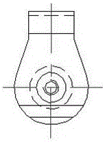
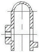
[0020] Example 1 : see Figure 1-Figure 5 , a spinning tube fixing device for a laying machine, the fixing device includes a spinning head 1, a spinning tube 2, a pipe clamp 3 and a fixing assembly, and the spinning tube is arranged on the spinning tube according to the Archimedes spiral On the head, the pipe clamp is arranged on the laying tube and the laying head, and the fixing assembly is used to fix the pipe clamp and the laying head. The fixing assembly includes a fixing pin 4 and a bolt 5, and the fixing pin 4 is arranged on In the pin holes of the pipe clamp and the spinning head, the bolts are arranged in the fixing pins. The fixing device can avoid collision between the pipe clamp of the laying machine and the protective cover, prevent the pipe clamp of the laying machine from being worn out, ensure the dynamic balance of the laying machine to be stable, and greatly reduce the vibration of the laying machine.

Embodiment 2

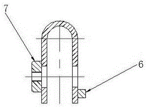
[0021] Example 2 : see Figure 1-Figure 5 , As an improvement of the present invention, the pipe clamp includes a weight block and a limit block 6, and the outer circle radius of the root of the pipe clamp is 30.5mm, which prevents collision with the protective cover and causes wear; the limit The position block and the pipe clamp are integrated to ensure that the weight of the original welded limit block is consistent; the bolt fixing block of the pipe clamp is integrally formed with the pipe clamp, which avoids the welding process and has good alignment with the pin hole; The number of the pipe clips is 13. The weighting block of the pipe clamp is integrated with the pipe clamp, which avoids the welding process, has high reliability, and will not cause desoldering during operation and use.

Embodiment 3

[0022] Example 3 : see Figure 1-Figure 5 , a method for installing a spinning tube fixing device for a laying machine, the installation steps are as follows: 1) first set the spinning tube on the spinning head according to the Archimedes helix; 2) set 13 tube jackets On the spinning tube and spinning head; 3) Insert the fixing pin into the pin hole of the spinning head and pipe clamp; 4) Insert the bolt into the fixing pin, and tighten the bolt to ensure the fixing between the pipe clamp and the spinning head Firm, the spinning tube is fixed by the limit between the tube clamp and the spinning head.

[0023] working principle:

[0024] see Figure 1-Figure 4 , the technical proposal proposes to remake the original pipe clamp into pipe clamp 3, and the radius of the outer circle of the root of pipe clamp 3 is reduced by 4mm to prevent collision with the protective cover and cause wear; the bolt fixing block 7 of the pipe clamp is integrated with the pipe clamp The weldin...


PUM

PropertyMeasurementUnit
radiusaaaaaaaaaa

Abstract

The invention relates to a fixing device for a loop laying tube of a loop laying machine. The fixing device is characterized by comprising a loop laying head body, the loop laying tube, tube clamps and a fixing assembly, wherein the loop laying tube is arranged at the loop laying head body according to Archimedes spiral; the tube clamps are arranged on the loop laying tube and the loop laying head body; the fixing assembly is used for fixing the tube clamps and the loop laying head body and comprises fixing pins and bolts, the fixing pins are arranged in pin holes of the tube clamps and the loop laying head body, and the bolts are arranged in the fixing pins. The fixing device can prevent bump between the tube clamps of the loop laying head and a protection cover, protects the tube clamps of the loop laying head from wearing, guarantees stable dynamic balance of the loop laying head and reduces vibration of the loop laying head greatly.

Description

technical field [0001] The invention relates to a fixing device, in particular to a fixing device for a laying tube of a laying machine, and belongs to the technical field of laying machine equipment for high-speed wire production. Background technique [0002] In the prior art, most of the wire rod factories adopt the American Morgan or the domestic imitation Morgan's laying machine to roll the high-speed wire rod. The laying head is one of the core equipment of the high-speed wire rod mill, and it is equipped with a vibration alarm. The vibration of the laying head directly affects the production efficiency of the high-speed wire rod. When rolling small specifications in the workshop, the line speed of the finished product is set at a high value. When it reaches or exceeds 100m / s, the laying machine will experience unstable vibration and imbalance, causing multiple alarms to stop, which will lead to early equipment failure. Problems such as damage, accelerated replacement...

Claims


Application Information

Patent Timeline
Patent Type & Authority Applications(China)
IPC IPC(8): B21C47/14
CPCB21C47/143
Inventor 卢正义倪瑞童向勇黄永祥付祯田俞永平张林
Owner JIANGSU YONGGANG GROUP CO LTD
Why Eureka
Try Eureka