Unbounded prestress and steel plate-concrete combined reinforcing design method of T-type beam

A design method and non-bonding technology, applied in bridge reinforcement, bridge construction, bridges, etc., can solve the problems of reducing the resonance effect between prestressed tendons and structures, high maintenance costs, and maintenance difficulties.

Active Publication Date: 2016-09-28
XIAN HIGHWAY INST
View PDF5 Cites 2 Cited by
  • Summary
  • Abstract
  • Description
  • Claims
  • Application Information

AI Technical Summary

Problems solved by technology

Although the above-mentioned external prestressed concrete reinforcement method can play the role of prestressed reinforcement to a certain extent, it has the following disadvantages: First, it is necessary to add a layer of concrete with a thickness of about 20cm to 50cm on the side or bottom of the beam. , the self-weight of the bridge increases greatly, and the appearance is irregular, which affects the appearance; second, the prestressed tendons are exposed in the air, and measures need to be taken regularly to prevent the prestressed tendons from rusting, maintenance is difficult, and the maintenance cost is high; third, the newly added The dynamic performance of prestressed tendons is poor, and shock absorbers need to be installed to reduce the resonance effect of prestressed tendons and structure

Method used


Image

  • Unbounded prestress and steel plate-concrete combined reinforcing design method of T-type beam
  • Unbounded prestress and steel plate-concrete combined reinforcing design method of T-type beam
  • Unbounded prestress and steel plate-concrete combined reinforcing design method of T-type beam

Examples


Embodiment Construction

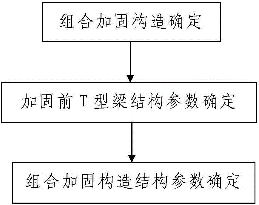
[0079] Such as figure 1 The design method of unbonded prestressed and steel plate-concrete combined reinforcement of a T-shaped beam includes the following steps:

[0080] Step 1. Combination reinforcement structure determination: determine the unbonded prestressed and steel plate-concrete composite reinforcement structure of the reinforced T-beam 3; the reinforced T-beam 3 is a reinforced concrete beam;

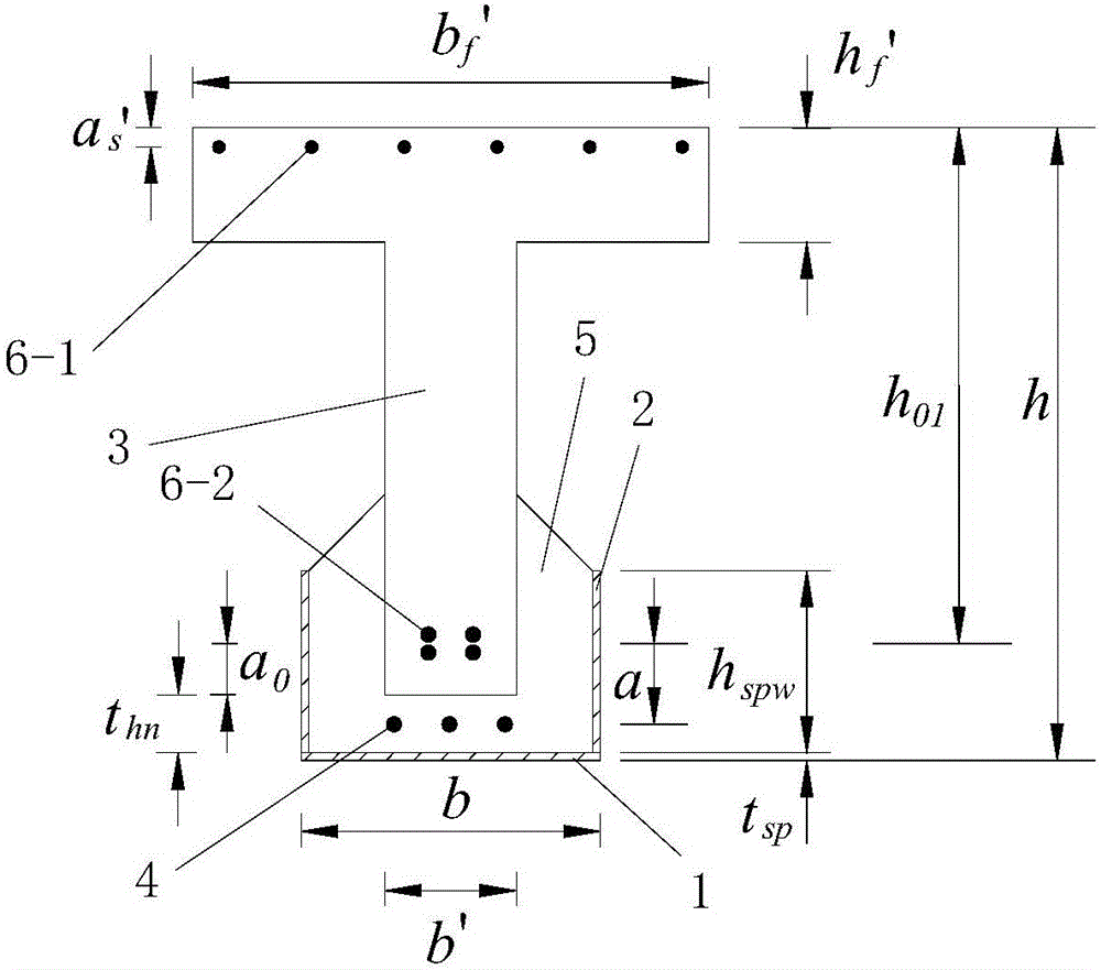
[0081] Such as figure 2 As shown, the combined reinforcement structure of unbonded prestress and steel plate-concrete includes a bottom steel plate 1 arranged under the area to be reinforced of the T-beam 3 to be reinforced, and two steel plates arranged on the left and right sides of the area to be reinforced respectively. The longitudinal side steel plates 2 and two end-blocking steel plates respectively arranged at the front and rear ends of the area to be reinforced, the bottom steel plate 1 and the two longitudinal side steel plates 2 are arranged in the longitudinal ...


PUM


Abstract

The invention discloses an unbounded prestress and steel plate-concrete combined reinforcing design method of a T-type beam. The method comprises the steps that first, a combined reinforcing structure is determined, specifically, the unbounded prestress and steel plate-concrete combined reinforcing structure of the reinforced T-type beam is determined and comprises a steel jacket box composed of a bottom steel board, two longitudinal side steel boards and two end portion sealing steel boards, and a plurality of unbounded prestress steel bars are arranged inside the steel jacket box; second, the structure parameters of the T-type beam are determined before reinforcement; and third, the structure parameters of the combined reinforcing structure are determined, specifically, the parameters are initialized, the maximum theory thickness of reinforcing steel boards is calculated, the thickness of the reinforcing steel boards and the thickness of concrete are determined, and the height of the longitudinal side steel boards and the width of the bottom steel board are determined. The method is simple in step, reasonable in design, convenient to implement, good in use effect, and capable of determining the structure parameters of the bridge combined reinforcing structure easily, conveniently and rapidly, and the designed bridge combined reinforcing structure is economical, practical and good in reinforcing effect.

Description

technical field [0001] The invention belongs to the technical field of bridge reinforcement, and in particular relates to a design method for the combined reinforcement of a T-shaped beam with unbonded prestress and steel plate-concrete. Background technique [0002] According to the survey in 2007, there are more than 570,000 bridges in my country, of which there are more than 98,600 dangerous bridges, accounting for about 17%. Affected by various diseases and disaster damage, resulting in a decline in carrying capacity, unable to meet the needs of transportation. It is imminent to repair and strengthen these bridge structures. Therefore, the research on bridge repair, reinforcement and transformation technology has become an important direction of bridge science and technology development. At present, the reinforcement of the upper structure of the bridge mainly adopts the methods of pasting steel plates and pasting carbon fiber cloth. During the reinforcement application ...

Claims


Application Information

Patent Timeline
IPC IPC(8): E01D22/00E01D19/00
CPCE01D19/00E01D22/00
Inventor 袁卓亚刘海鹏石雄伟秦军许冰冯威柯亮亮雷丹田丞
Owner XIAN HIGHWAY INST
Why Eureka
Try Eureka