Wave power generation device using spiral structure and working method thereof

A technology of power generation device and spiral structure, which is applied in the fields of ocean energy power generation, engine function, engine components, etc., can solve problems such as damage to device parts, and achieve the effects of stable operation, good corrosion resistance and environmental protection.

Inactive Publication Date: 2016-09-28
SHANDONG UNIV OF SCI & TECH
View PDF10 Cites 7 Cited by
  • Summary
  • Abstract
  • Description
  • Claims
  • Application Information

AI Technical Summary

Problems solved by technology

[0007] Investigating the existing ocean energy power generation device, Chinese patent CN102678430A proposes a scroll spring group of a wave energy generation device, through which the energy generated by the power transmission mechanism is stored and released, but it ignores the large The energy transmitted by the wave is too large and exceeds the threshold of the scroll spring group, resulting in damage to the components of the device

Method used


Image

  • Wave power generation device using spiral structure and working method thereof
  • Wave power generation device using spiral structure and working method thereof
  • Wave power generation device using spiral structure and working method thereof

Examples


Embodiment 1

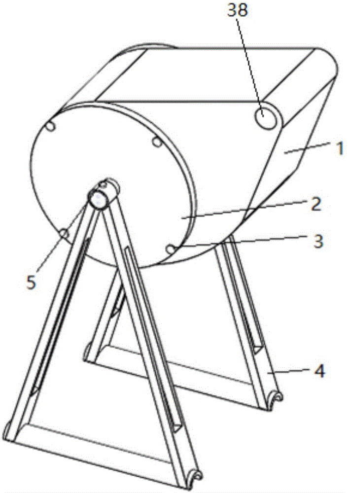
[0071] A wave energy generating device utilizing a spiral structure, comprising a wave energy collector, a bracket connected to the wave energy collector, a wave energy conversion main mechanism arranged inside the wave energy collector, an energy transmission device and an energy output device;

[0072] The wave energy collector includes a cavity and a cam body arranged outside the cavity, and the cavity is a cylindrical cavity;

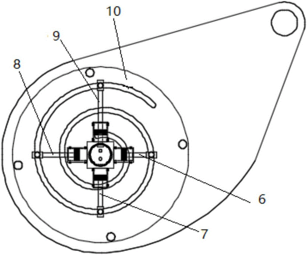
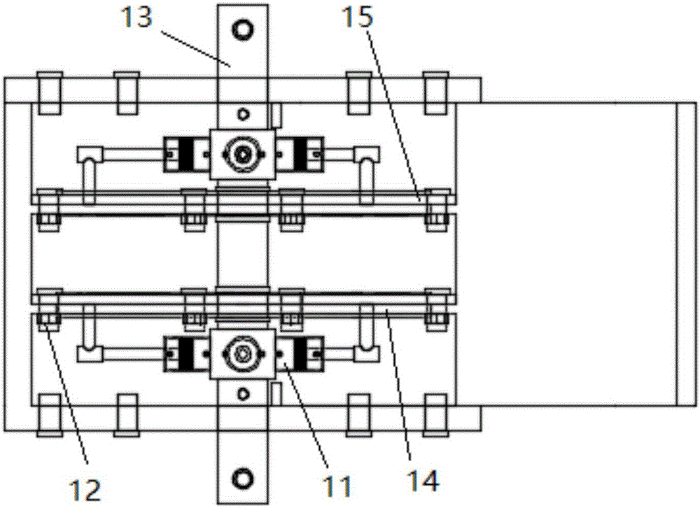
[0073] The main mechanism of wave energy conversion is located in the cylindrical cavity. The main mechanism of wave energy conversion is provided with a fixed shaft. The main mechanism of wave energy conversion includes a screw turntable, a piston rod group, and a hydraulic cylinder. The hydraulic cylinder is connected with the fixed shaft. The bracket bolt group is connected with the bracket, the screw turntable is connected with the piston rod group, the piston rod group is connected with the hydraulic cylinder, and the screw turntable is connecte...

Embodiment 2

[0078] A wave energy power generation device using a spiral structure, the structure is as described in Embodiment 1, the difference is that the cam body of the wave energy harvester is provided with ups and downs and floating holes. Floating bodies such as foam plastics can be added to the heave and float holes, so that the heave and float holes will heave up and down with the heave motion of the wave, which is specifically manifested as the swing of the wave energy harvester around the fixed axis, so that the wave energy harvester can control the wave's rise and fall. The potential energy of the sinking motion is transformed into the mechanical energy of its own swing. In addition, the kinetic energy of the wave impact movement captured by the wave energy harvester makes the wave energy harvester have a higher wave energy capture capability.

Embodiment 3

[0080] A wave energy generating device using a spiral structure, the structure is as described in Embodiment 1, the difference is that the wave energy generating device utilizing a spiral structure also includes a support baffle, and the support baffle is arranged outside the main wave energy conversion mechanism At both ends, the wave energy conversion main mechanism is bolted to the wave energy harvester through the support baffle, and the support baffle is connected to the fixed shaft through the bearing. The support baffle is located at the outermost side of the main wave energy conversion mechanism, and is fixedly connected to the wave energy harvester through the support baffle bolt group to play the role of support and sealing, and at the same time swings with the swing of the wave energy harvester.


PUM


Abstract

The invention relates to a wave power generation device using a spiral structure and a working method thereof, and belongs to the technical field of power generation devices. The device comprises a wave energy collector, a support connected with the wave energy collector, main wave energy conversion mechanisms arranged inside the wave energy collector, an energy transfer device and an energy output device. The main wave energy conversion mechanisms comprise spiral rotary tables, piston rod sets and hydraulic cylinders. The hydraulic cylinders are connected with a fixed shaft, and the fixed shaft is connected with the support through a support bolt set. The spiral rotary tables are connected with the piston rod sets. The piston rod sets are connected with the hydraulic cylinders. The spiral rotary tables are connected with the fixed shaft through bearings. The main wave energy conversion mechanisms absorb wave energy to drive oil to arrive at an energy accumulator and a hydraulic motor in the energy transfer device, and the hydraulic motor is driven to act so that the energy output device, namely an electric generator can be driven to generate electricity. The wave power generation device is scientific and simple, stable to operate, high in reliability, good in safety, high in conversion rate and beneficial to popularization.

Description

technical field [0001] The invention relates to a wave energy generating device utilizing a spiral structure and a working method thereof, belonging to the technical field of generating devices. Background technique [0002] With the progress of science and the development of economy, the energy crisis of human society is becoming more and more serious. The development and utilization of green renewable energy is an important way to solve the energy shortage. As an environmentally friendly and all-weather new energy, wave energy has been increasingly valued by various countries. Wave energy utilization technology can be divided into power generation, hydrogen production, heating, seawater desalination, water pumping, etc. according to its final utilization form, among which wave energy power generation is the main utilization form. In the development process of wave energy generation utilization technology, wave energy generation devices have always been the research focus ...

Claims


Application Information

Patent Timeline
Patent Type & Authority Applications(China)
IPC IPC(8): F03B13/14
CPCF03B13/14F05B2260/406Y02E10/30
Inventor 陈修龙宋浩姜帅王清王兵振
Owner SHANDONG UNIV OF SCI & TECH
Why Eureka
Try Eureka