An Uninterruptible Power Exchanger for AC Power Distribution System

A technology of AC power distribution and AC circuit breaker, which is applied in the direction of electrical components, circuit devices, emergency power supply arrangements, etc., can solve the problems of large reserve capacity and low utilization rate of equipment, achieve powerful functions, improve utilization efficiency, facilitate planning and The effect of construction

Active Publication Date: 2018-10-19
TSINGHUA UNIV
View PDF4 Cites 0 Cited by
  • Summary
  • Abstract
  • Description
  • Claims
  • Application Information

AI Technical Summary

Problems solved by technology

[0004] The purpose of the present invention is to propose a kind of uninterruptible power exchanger for AC power distribution system from the aspect of distribution network construction, aiming at the problems of large backup capacity of the main transformer and low equipment utilization rate in the existing AC power distribution system. In order to effectively reduce the backup capacity of the main transformer, improve the utilization rate of power distribution network equipment, realize uninterrupted power supply under the system N-1 failure, and realize the active optimization control of the system power flow (power), improve the quality of power supply and ensure that the AC system can Flexible reactive power compensation for faults

Method used


Image

  • An Uninterruptible Power Exchanger for AC Power Distribution System
  • An Uninterruptible Power Exchanger for AC Power Distribution System
  • An Uninterruptible Power Exchanger for AC Power Distribution System

Examples


Embodiment Construction

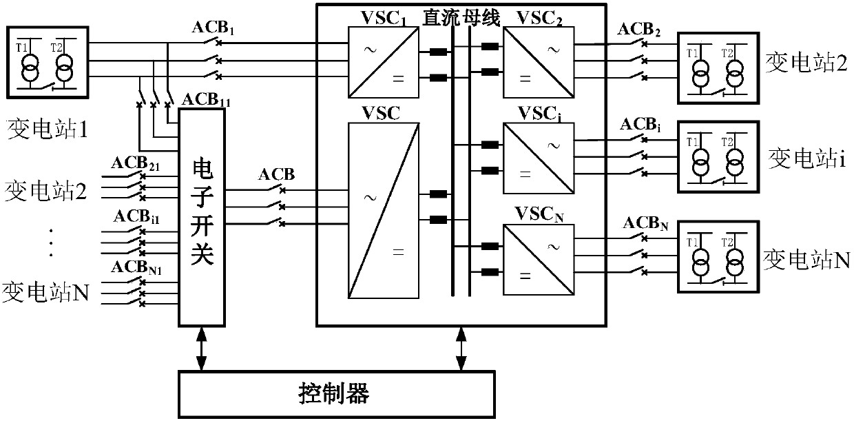
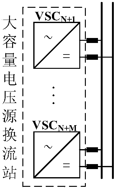
[0019] The uninterrupted power exchanger used in the AC power distribution system proposed by the present invention, its circuit diagram is as follows figure 2 As shown, it includes N small-capacity voltage source converter stations, one large-capacity voltage source converter station, an electronic switch and a controller; the AC sides of the N small-capacity voltage source converter stations are respectively passed through N AC circuit breakers are connected to corresponding AC substations in the AC power distribution system, and the DC sides of N small-capacity voltage source converter stations are respectively connected to the DC buses of the uninterruptible power exchanger through DC circuit breakers; the large-capacity The AC side of the voltage source converter station is connected to one end of the electronic switch through an AC circuit breaker, and the DC side of the large-capacity voltage source converter station is connected to the DC bus of the uninterruptible pow...


PUM


Abstract

The invention relates to an uninterrupted electric power exchanger used for an alternating current power distribution system, and belongs to the technical field of a combination of electric power electronics and a power distribution technology. The uninterrupted electric power exchanger comprises a small-capacity VSC, a high-capacity VSC, an electronic switch and a controller, wherein the alternating current side of the small-capacity VSC is connected with a corresponding alternating current substation through an alternating current circuit breaker while the direct current side of the small-capacity VSC is connected with the direct current bus of the uninterrupted electric power exchanger; the alternating current side of the high-capacity VSC is connected with one end of the electronic switch while the direct current side of the high-capacity VSC is connected with the direct current bus of the uninterrupted electric power exchanger; the other end of the electronic switch is connected with the corresponding alternating current substation through the alternating current circuit breaker; and the controller is connected with the electronic switch, the small-capacity VSC and the high-capacity VSC separately through signal lines. By adoption of the electric power exchanger, the utilization efficiency of a single main transformer is improved, the total capacity of the voltage source convertor station is reduced, the overall loss of the system is lowered, the total investment amount of the equipment is reduced, and the more economic and reliable operation of the overall equipment is achieved.

Description

technical field [0001] The invention relates to an uninterrupted power switch for an AC power distribution system, belonging to the technical field of combining power electronics and power distribution technology. Background technique [0002] In recent years, with the continuous expansion of city scale and the rapid increase of power load, the requirements for power quality, power supply reliability and transmission capacity of power distribution network are also increasing. In response to these requirements, there are two main ideas for the development of the distribution network: 1) develop distributed power sources and supporting facilities to reduce the pressure on the distribution network; 2) strengthen the construction of the distribution network and increase the utilization rate of distribution equipment. At present, many experts and scholars are studying the flexible access of distributed power sources. Common distributed power sources mainly include photovoltaic ce...

Claims


Application Information

Patent Timeline
Patent Type & Authority Patents(China)
IPC IPC(8): H02J9/02
CPCH02J9/02
Inventor 袁志昌季一润王一振付姣朱俊宇
Owner TSINGHUA UNIV
Why Eureka
Try Eureka