Photovoltaic-coupled distributed energy system of internal combustion machine

A distributed energy and internal combustion engine technology, applied in solar heating systems, photovoltaic power generation, machine operation methods, etc., can solve problems such as system efficiency not reaching the design effect, unacceptable on-grid electricity prices, and difficulties in accessing the Internet. Improve overall operating efficiency, improve energy utilization, and reduce equipment costs

Inactive Publication Date: 2020-09-22
STATE GRID ENERGY CONSERVATION SERVICE +1
View PDF13 Cites 3 Cited by
  • Summary
  • Abstract
  • Description
  • Claims
  • Application Information

AI Technical Summary

Problems solved by technology

Although the combined cooling, heating and power supply in the distributed energy system can greatly improve the energy efficiency of the system under the design working conditions, because the user end has multiple demands for cooling, heating and electricity, and the three aspects of the distributed energy system The three output products cannot be matched arbitrarily. The three products are interrelated and restrict each other. For example, when the demand for electricity is large, a large amount of heat will be generated at the same time. In order not to waste electricity, it is necessary to purchase electricity from the public grid; and when the demand for electricity is small and the cooling and heating loads are large, it is necessary to connect the combined heat and power unit to the public grid to sell the rich electricity, which has the problem of grid connection. , for distributed energy systems that are far away from the large power grid or are small in scale, the problem of accessing the grid is especially difficult
However, my country is a gas-poor country, and the price of natural gas is relatively high. Even if the gas-steam combined cycle is used to produce electricity with a high efficiency of 55%, its on-grid electricity price is still unacceptable.
[0003] Distributed energy systems are often installed close to the user, and are easily affected by changes in the cooling, heating, and electricity demands of the user during operation. They operate at low load for a long time. As a result, the efficiency of the system in the entire operating cycle cannot reach the design effect

Method used


Image

  • Photovoltaic-coupled distributed energy system of internal combustion machine

Examples


Embodiment 1

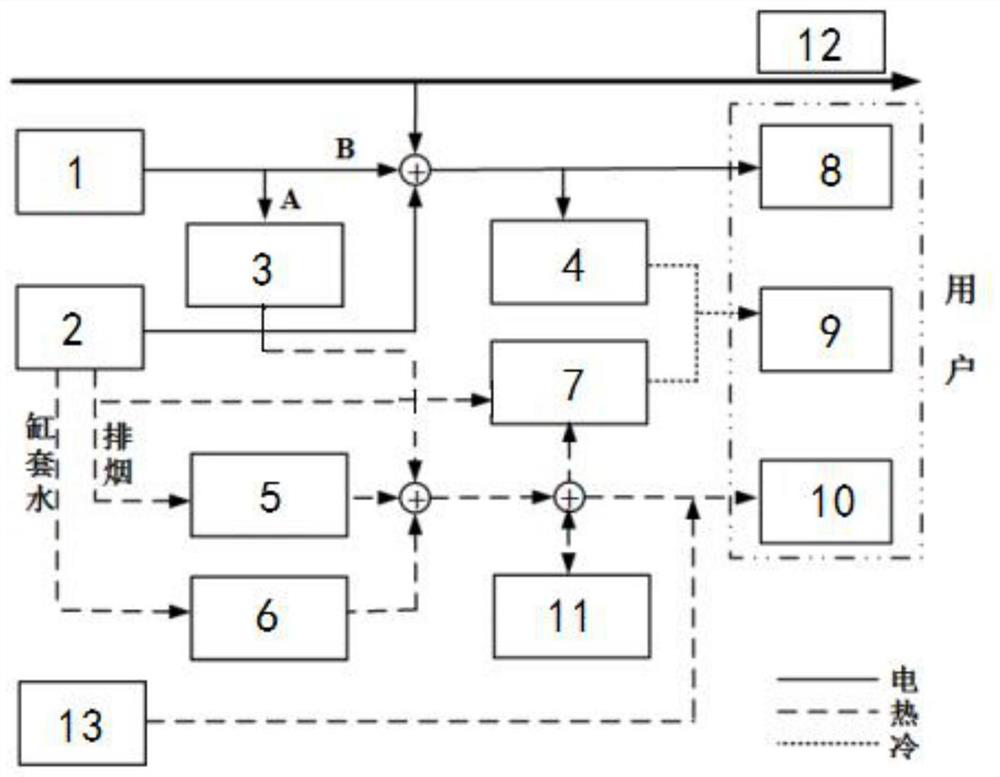
[0031] like figure 1 As shown, a photovoltaic-coupled internal combustion engine distributed energy system shown in this embodiment includes: photovoltaic module 1, gas internal combustion engine 2, electric heater 3, electric refrigeration unit 4, smoke-water heat exchanger 5, water-water heat exchanger 6. Flue gas hot water type absorption refrigeration unit 7, electrical load 8, cooling load 9 and heat load 10.

[0032] The electricity generated by the photovoltaic module 1 is divided into two paths, A path and B path, and the A path is connected to the electric heater 3 to generate hot water; the B path is combined with the electricity generated by the gas internal combustion engine 2 and then divided into two branches. One branch is connected to the electric refrigeration unit 4 to generate cold water, and the other branch is connected to the electric load 8 at the user end.

[0033] After the B circuit is combined with the electricity generated by the gas internal combu...


PUM


Abstract

The invention relates to a photovoltaic-coupled distributed energy system of an internal combustion machine. The system comprises a photovoltaic assembly, the gas internal combustion engine, an electric heater, an electric refrigeration unit, a smoke-water heat exchanger, a water-water heat exchanger, a smoke hot-water-type absorption-type refrigeration unit, electrical loads, cooling loads, heating loads, a power grid, a hot water tank and a gas-fired boiler. Electric energy generated by the photovoltaic assembly, electric energy and heat energy produced by the gas internal combustion engineand heat energy produced by the gas-fired boiler are directly transmitted or are transformed through the electric refrigeration unit, the smoke-water heat exchanger, the water-water heat exchanger, and the smoke hot-water-type absorption-type refrigeration unit in the system, so that the dynamically changing demands for cooling loads, heating loads and electrical loads at the user side are met,. The system is stable and reliable in operation and more flexible to adjust, running under different conditions of proportions of cooling loads, heating loads and electrical loads at the user side is adapted to, and therefore, the utilization rate of each set of equipment in the whole system and the energy efficiency for overall system operation are increased, and the system cost is lowered.

Description

technical field [0001] The invention relates to the field of energy utilization, in particular to an internal combustion engine distributed energy system coupled with photovoltaics Background technique [0002] Distributed energy systems based on comprehensive cascade utilization of energy and featuring high efficiency, environmental protection, economy, reliability and flexibility have received extensive attention and certain applications. Although the combined cooling, heating and power supply in the distributed energy system can greatly improve the energy efficiency of the system under the design working conditions, because the user end has multiple demands for cooling, heating and electricity, and the three aspects of the distributed energy system The three output products cannot be matched arbitrarily. The three products are interrelated and restrict each other. For example, when the demand for electricity is large, a large amount of heat will be generated at the same t...

Claims


Application Information

Patent Timeline
Patent Type & Authority Applications(China)
IPC IPC(8): F23J15/06F24S20/40F24S80/00F25B15/04F25B21/00H02J3/38
CPCF23J15/06F24S80/00F25B21/00F25B15/04H02J3/381F24S20/40H02J2300/24Y02E10/40Y02E10/56Y02E20/30Y02A30/27Y02B30/00Y02B30/62
Inventor 白保华张军宏范滢彭勇蒋剑峰殷仁鹏王锡侯宏娟
Owner STATE GRID ENERGY CONSERVATION SERVICE
Why Eureka
Try Eureka