Al technical title is built by PatSnap Al team. It summarizes the technical point description of the patent document.
A 3D printer, rotary technology, applied in ceramic molding machines, manufacturing tools, additive processing, etc., can solve the problem of large volume, printing nozzle control accuracy, printing nozzle movement speed is difficult to achieve, printing nozzle spatial position control reliability Low-level problems, to achieve the effect of concise overall structure, improved space utilization, and improved printing speed
Active Publication Date: 2016-10-05
南通三聚知识产权服务有限公司
View PDF8 Cites 11 Cited by
Summary
Abstract
Description
Claims
Application Information
AI Technical Summary
This helps you quickly interpret patents by identifying the three key elements:
Problems solved by technology
Method used
Benefits of technology
Problems solved by technology
Another example is that the authorized announcement number CN203485190U provides "a 3D printer based on a parallel mechanism". Because the patented solution uses a servo motor (paragraph 0016 of the specification), it is not only large in size, but also reliable in controlling the spatial position of the printing nozzle. Low
Furthermore, as the invention patent application publication number CN103862679A introduces a "3D printer", the patent application evaluates the aforementioned CN103317726A in paragraph 0004 of its description, and the technical solution it provides (paragraphs 0006 to 0012 of the description) overcomes the disadvantages of CN103317726A. However, because the patent application scheme uses a stepping motor to drive the print head to move, the control accuracy of the print head and the speed at which the print head is driven are difficult to achieve the desired effect in the industry
Method used
Image
Click on the blue label to locate the original text in one second.
Reading with bidirectional positioning of images and text.
Examples
Embodiment Construction
[0020] In order to enable the examiners of the patent office, especially the public, to understand the technical essence and beneficial effects of the present invention more clearly, the applicant will describe in detail the following in the form of examples, but none of the descriptions to the examples is an explanation of the solutions of the present invention. Any equivalent transformation made according to the concept of the present invention which is merely formal but not substantive shall be regarded as the scope of the technical solution of the present invention.
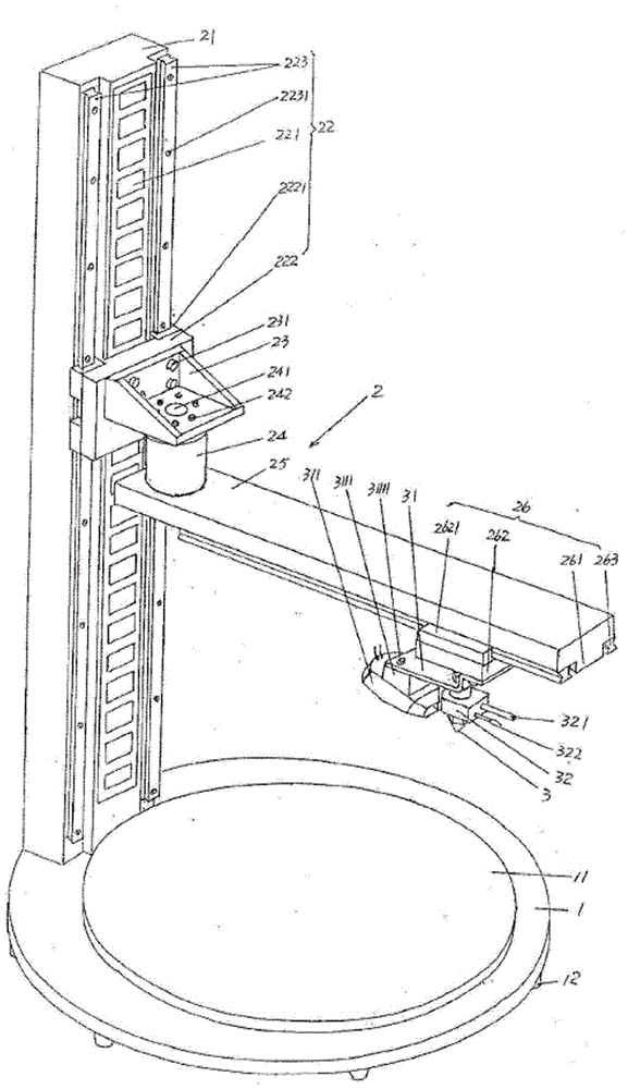
[0021] See figure 1 ,exist figure 1 A base 1 of the structural system of the rotary 3D printer of the present invention is shown in , on the base 1 and on the upward side of the base 1 is provided a stage 11 for carrying printed objects, the stage 11 Also known as the printing platform, as a preferred solution, the base vacating flange 12 can also be set at the bottom of the base 1; a print head platform d...
PUM
Property
Measurement
Unit
thickness
aaaaa
aaaaa
Abstract
The invention discloses a rotary-type 3D (three-dimensional) printer, and belongs to the fused deposition quick molding equipment. The rotary-type 3D printer comprises a base, a printing head platform drive mechanism and a printing head, wherein an objective table is arranged on the base, the printing head platform drive mechanism is arranged on the base, and the printing head is arranged on the printing head platform drive mechanism. The printing head platform drive mechanism comprises a linear motor base, a linear motor, a rotary motor base, a rotary motor, a rotary arm and a printing head platform horizontal moving motor, wherein the linear motor is fixed on the base and arranged at one side, towards the rotary arm, of the linear motor base, the rotary motor base is fixed on the linear motor, the rotary motor is fixed on the rotary motor base, a rotary motor shaft is fixed with one end, towards the linear motor, of the rotary arm, the other end of the rotary arm is corresponding to a position above the objective table, the printing head platform horizontal moving motor is arranged at one side, towards the objective table, of the rotary arm, and the printing head is fixed on the printing head platform horizontal moving motor. The rotary type 3D printer disclosed by the invention can be used for improving the printing speed, printing high-precision components and precisely controlling the radius, the angle and the height, and is high in space utilization rate.
Description
[0001] This application is a divisional application of an invention patent application named: rotary 3D printer, application date: November 21, 2014, and application number: 201410674487.1. technical field [0002] The invention belongs to the technical field of fusion deposition rapid prototyping equipment, and in particular relates to a rotary 3D printer. Background technique [0003] Because 3D printing integrates cutting-edge technical knowledge in digital modeling technology, electromechanical control technology, information technology, material science and chemistry, etc., it makes large-scale personalized production possible and leads a major change in the global manufacturing economy. widely received people's attention. 3D printer is the core equipment of 3D printing. It uses consumables (consumables such as: powdered metal materials, plastics, ceramics, sand and other bondable materials) based on digital model files to build objects by layer-by-layer printing. Th...
Claims
Application Information
Patent Timeline
Application Date:The date an application was filed.
Publication Date:The date a patent or application was officially published.
First Publication Date:The earliest publication date of a patent with the same application number.
Issue Date:Publication date of the patent grant document.
PCT Entry Date:The Entry date of PCT National Phase.
Estimated Expiry Date:The statutory expiry date of a patent right according to the Patent Law, and it is the longest term of protection that the patent right can achieve without the termination of the patent right due to other reasons(Term extension factor has been taken into account ).
Invalid Date:Actual expiry date is based on effective date or publication date of legal transaction data of invalid patent.