Rim-control type electric bike and drive, brake and range extending methods thereof

A technology for electric vehicles and rims, which is applied in the control of driving, electric vehicles, motor vehicles, etc., can solve the problems of unrealistic continuation mileage, short continuation mileage, and restrictions, and achieves overcoming short continuation mileage and diversified combinations. , the effect of simple structure

Inactive Publication Date: 2016-10-05
东莞恒量新能源科技有限公司
View PDF4 Cites 0 Cited by
  • Summary
  • Abstract
  • Description
  • Claims
  • Application Information

AI Technical Summary

Problems solved by technology

However, when this waterwheel model was translated to the field of electric vehicles, it did not achieve the expected development success
For example, an electric bicycle with teeth on the outer edge of the rim and a geared motor on the output shaft is installed on the market, and the shaft output power of the motor is transmitted through the gears. Power supply, its electric energy conversion efficiency is similar to that of the wheel hub motor, and setting the motor on the outer edge of the rim will be limited by power
[0005] Short mileage is the weakness of electric vehicles at this stage. The industry generally believes that before high-energy batteries enter commercial use, it is unrealistic to increase the mileage of electric vehicles by increasing the number of batteries. Therefore, the current mainstream of the automobile market is to develop a dual-source hybrid of oil and electricity. The design concept of the car is: when the car starts or at low speed, the power of the electr...

Method used


Image

  • Rim-control type electric bike and drive, brake and range extending methods thereof
  • Rim-control type electric bike and drive, brake and range extending methods thereof
  • Rim-control type electric bike and drive, brake and range extending methods thereof

Examples


Embodiment 1

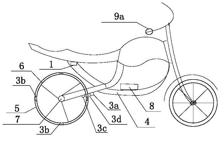
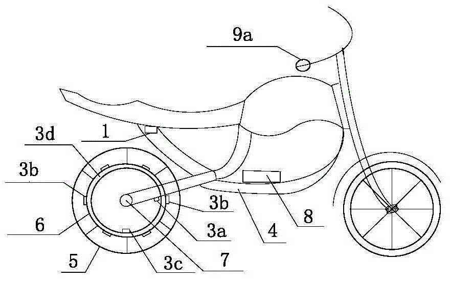
[0092] An electric two-wheeled vehicle with a front and rear two-wheel structure. Figure 1a The frame 4 shown is a wheel 5 with a circumference of 1000mm. The electric device is designed as a combination of a stator unit 3a and eight permanent magnet rotor units 3b on the rim 6. The rotor unit is arranged on the outer edge of the rim, and the stator unit is installed On the frame at the inner edge of the rear wheel.

[0093] The battery pack is made of 24V10Ah lithium iron phosphate battery, which is installed in a special place in the frame.

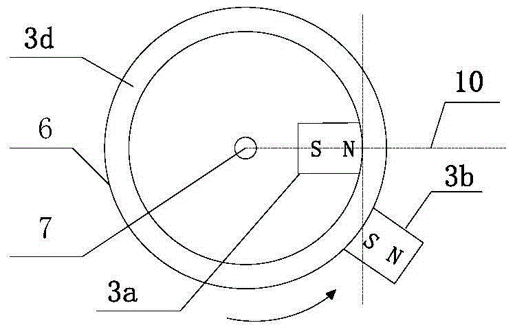
[0094] The length of the permanent magnet rotor unit 3b is 20mm, and the width takes the maximum value without affecting the outer rubber wheel of the rim. It is tightly installed on the outer edge of the rim 6 made of titanium-aluminum alloy. The tangent lines of the circles are parallel, and the S poles of the eight rotor units all face the direction of rotation of the wheel 5; the stator unit core material is a concave ferromagnet t...

Embodiment 2

[0102] Embodiment 1 is provided with an electromagnetic brake function.

[0103] The electromagnetic braking device 9b is a ten-stage rheostat, and the power modulator correspondingly adds a braking signal input terminal 1e to be electrically connected with the electromagnetic braking device, such as Figure 5c shown. The braking logic of the power modulator is: when the manual control electromagnetic brake device sends out a braking signal, the power modulator cuts off the T 1 corresponding to the timing current while starting T 2 time domain power-up, the T 2 The time domain is set as the time period when the sensing unit 3c senses the rotor unit 3b around the axis to the position where θ is from 30 degrees to θ is 0 degrees. The braking current output by the power modulator corresponds to the ten-level resistance setting of the electromagnetic braking device as ten-level intensity, and the output current intensity is set as: the first level is 6A, the last level is 12A, ...

Embodiment 3

[0106] The braking logic of Embodiment 2 is further optimized as follows: the power modulator starts T 2 While powering up in the time domain, the T 0 part of the time domain operating logic is synchronously transformed for power-up, the T 0 Part of the time domain value and (T 1 +T 2 ) are equal, T 0 The moment of energization starts when θ is 0; the power modulator starts at this T 0 The intensity of the braking current output in part of the time domain and T 2 Same time domain. In this embodiment, the time-domain energization of the rotor unit away from the state of the stator unit is added, and the electromagnetic braking / braking effect of the electric device is strengthened, and the corresponding period sequence can be briefly set as: in (T 1 +T 2 +T 0 ) timing, the initial 1 / 3 of T 1 time domain power down, after 2 / 3 of (T 2 +T 0 ) time domain energization. .

[0107] In this embodiment, the winding of the stator unit is changed to a double-wire winding core...


PUM

PropertyMeasurementUnit
Diameteraaaaaaaaaa

Abstract

The invention discloses an electric bike controlled through an electric rim. The electric bike comprises a power source modulator, a drive control unit, a frame, a battery pack and at least one wheel. At least one wheel of the electric bike is provided with an electric actuator which comprises stator units and permanent magnet rotor units. At least one rotor unit is arranged on the rim of the wheel; at least one stator unit is arranged on a fixing portion of the frame; and the periodical relative air-gap between the stator unit and the rotor unit is not greater than 90 mm. The battery pack includes a primary battery and a secondary battery or combination of the two. The electromagnetic pole direction of the stator unit is opposite to the electromagnetic pole in movement direction of the rotor unit. The power source modulator acquires users' instructions and outputs sequence current correspondingly through the drive control unit/electromagnetic brake device so as to achieve drive/brake of the electric bike. A range extending system of the electric bike adopts a secondary battery pack for power supplement.

Description

technical field [0001] The invention relates to the field of electric vehicles and their power supply power design, in particular to an electric vehicle with an electric device arranged on a wheel rim and its driving, braking and range-extending methods. Background technique [0002] At present, the number of electric bicycles in my country has reached more than 150 million, and the number of electric tricycles has exceeded 10 million. Regional electric four-wheel vehicles are developing rapidly. [0003] Electric vehicles in the market are generally equipped with permanent magnet brushless motors, and the industry chain of accessories is mature, and is currently developing from general-purpose to professional design. The mainstream of the electric bicycle market is equipped with hub motors. The industry generally believes that the technology of hub motors has matured, and the main competition focuses on the control of material and labor costs. For motor control, PWQ techno...

Claims


Application Information

Patent Timeline
IPC IPC(8): B62M7/12B60L15/00
Inventor 刘粤荣姚飞
Owner 东莞恒量新能源科技有限公司
Why Eureka
Try Eureka