
Engine device

A technology of engine and exhaust gas purification device, which is applied in the direction of power plant, engine components, combustion engine, etc., can solve the problem that the DPF box or SCR box cannot be compactly supported, and achieve the effect of improving maintenance workability and suppressing the cost of parts

Inactive Publication Date: 2016-10-05
YANMAR POWER TECHNOLOGY CO LTD
View PDF9 Cites 1 Cited by
  • Summary
  • Abstract
  • Description
  • Claims
  • Application Information

AI Technical Summary

Problems solved by technology

[0012] On the other hand, when the DPF case and the SCR case are assembled close to the engine, there is a problem that it is easy to maintain the temperature of the exhaust gas in the SCR case while reducing the temperature drop of the exhaust gas supplied from the engine to the SCR case. It is high temperature, but it is necessary to ensure the installation space for the SCR box on the side of the engine, and it cannot support the DPF box or the SCR box compactly.

Method used


Image

  • Engine device
  • Engine device
  • Engine device

Examples


Embodiment Construction

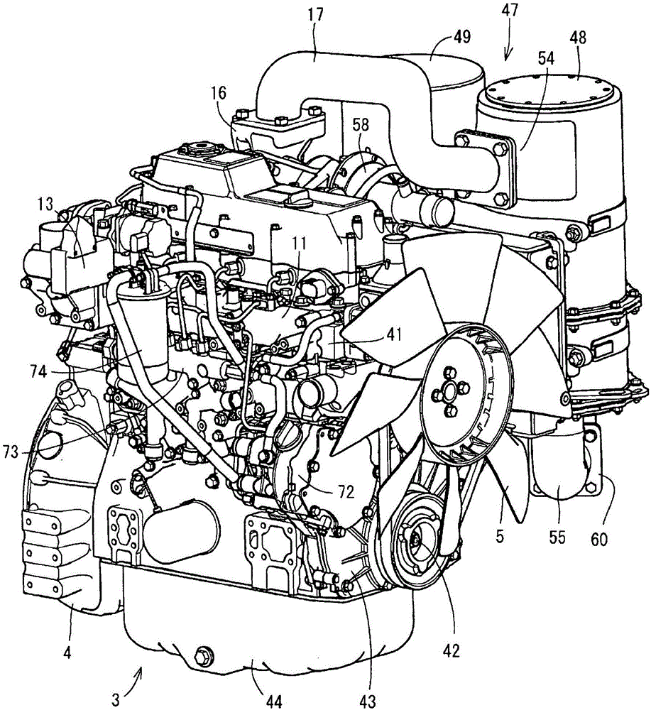
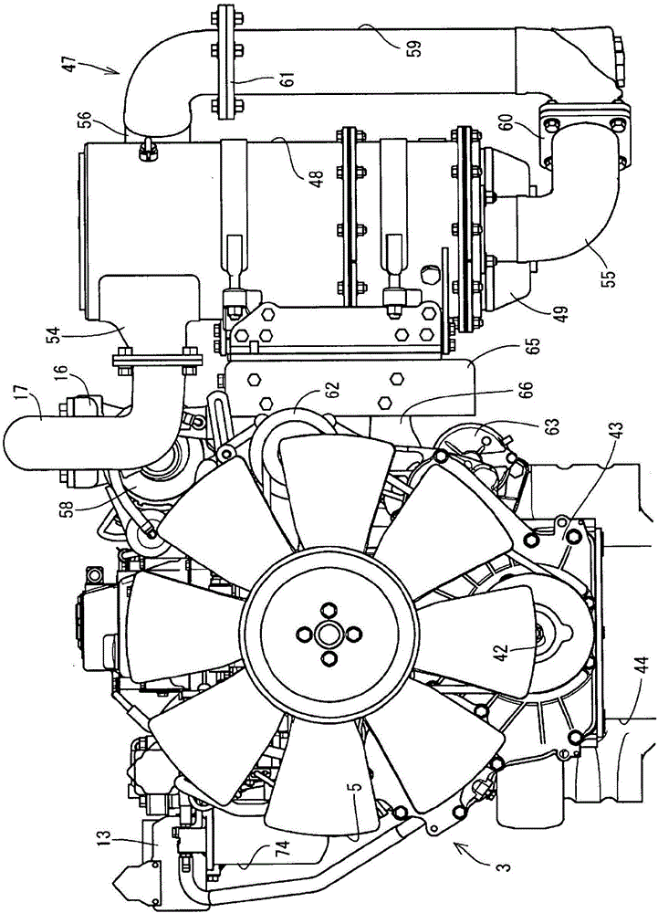
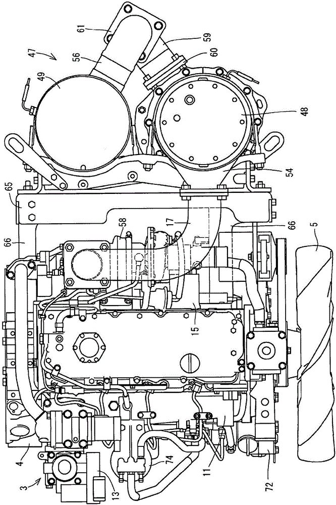
[0051] Below, refer to Figure 1 to Figure 6 , the first embodiment of the engine device of the present invention will be described based on the drawings. Figure 1 ~ Figure 3 It is an explanatory diagram showing the diesel engine of the first embodiment, Figure 4 ~ Figure 6 It is an explanatory diagram of a stationary power generation working machine 70 equipped with the above-mentioned diesel engine and generator.

[0052] refer to Figure 4 ~ Figure 6 , the structure of the stationary power generation working machine 70 of the first embodiment will be described. Such as Figure 4 ~ Figure 6 As shown, a square box-shaped casing 2 is placed on the casing platform 1 . A diesel engine 3 is arranged in the center of the inside of the casing 2 on the upper surface of the machine frame platform 1 . The radiator 6 is arranged on the side where the cooling fan 5 is installed on the front side of the diesel engine 3 . A generator 18 , which will be described later, is disposed...


PUM


Abstract

The purpose of the present invention is to provide an engine device in which an engine (3) and an exhaust gas purification device (47) can be placed in a compact manner inside a machine housing (2) of a stationary power-generating work machine (70), for example, while allowing the maintainability on the upper surface side of the engine (3) to be improved. This engine device comprises: a first case (48) that removes particulate matter in an exhaust gas of an engine (3); and a second case (49) that removes nitrogen oxides in the exhaust gas of the engine (3). The second case (49) is connected to the first case (48) via a urea mixing pipe (59). The engine device comprises a support mount (65) for firmly fixing the first case (48), the second case (49), and the urea mixing pipe (59) in a parallel manner. The first case (48), the second case (49), and the urea mixing pipe (59) are arranged integrally on the support mount (65), to form an exhaust gas purification device (47) having a single-component structure, and the exhaust gas purification device (47) is attached to a support leg (66) provided to the engine (3).

Description

technical field [0001] The present invention relates to an engine device such as a diesel engine mounted on agricultural machinery (tractor, combine harvester) or construction machinery (bulldozer, hydraulic excavator, loader), etc., and more specifically relates to an engine device equipped with a device for removing particulate matter contained in exhaust gas. (Smoke dust, particulates) or exhaust gas purification equipment such as nitrogen oxides (NOx) contained in exhaust gas. Background technique [0002] In work vehicles such as tractors and wheel loaders, in order to improve the efficiency of maintenance work on the engine disposed at the front of the traveling body, an opening and closing fulcrum shaft is arranged at the rear of the engine hood that covers the engine so that the engine hood The opening and closing fulcrum shaft rotates. In addition, conventionally, in the exhaust path of a diesel engine, as an exhaust gas purification device (exhaust gas after-treat...

Claims


Application Information

Patent Timeline
Patent Type & Authority Applications(China)
IPC IPC(8): F01N3/28B01D53/86E02F9/00F01N3/02F01N3/08F01N3/24F01N13/08F02B67/00A01D41/12
CPCB60K13/04E02F9/0866F01N3/02F01N3/08F01N13/009F01N13/1805F01N2340/04F01N2450/08F01N2470/18F01N2590/08F01N2590/10Y02T10/12B01D46/001B01D46/0027B01D53/9431B01D2279/30F01N3/035F01N3/2066F01N13/18F01N2250/02F01N2610/02
Inventor 末藤宽士
Owner YANMAR POWER TECHNOLOGY CO LTD
Learn More