
Preparation method for fiber bragg grating magnetic sensor based on reflow soldering

A fiber grating and magnetic sensor technology, which is used in welding equipment, measurement and instrumentation by measuring the changing force of optical properties of materials when they are stressed, can solve the problem of low composite efficiency of fiber grating and magnetostrictive film, affecting magnetostriction Stress changes of the telescopic film, uneven artificial coating of epoxy resin glue, etc., to achieve long-term stable mechanical connection, good performance, and novel solutions

Active Publication Date: 2016-10-12
HUAZHONG UNIV OF SCI & TECH
View PDF5 Cites 1 Cited by
  • Summary
  • Abstract
  • Description
  • Claims
  • Application Information

AI Technical Summary

Problems solved by technology

The main problem of the traditional composite method is the low composite efficiency of the fiber grating and the magnetostrictive film, which is mainly manifested in the following three points: (1) the Young's modulus of the epoxy resin is relatively low, and the size of the Young's modulus is related to the composite efficiency It is positively correlated; (2) The epoxy resin glue is artificially applied unevenly, which will affect the transmission of the stress change of the magnetostrictive film; (3) There is a hidden danger that the epoxy resin will become unstable after a long time of pasting. This will seriously affect the recombination efficiency of the fiber grating

Method used


Image

  • Preparation method for fiber bragg grating magnetic sensor based on reflow soldering
  • Preparation method for fiber bragg grating magnetic sensor based on reflow soldering
  • Preparation method for fiber bragg grating magnetic sensor based on reflow soldering

Examples


Embodiment Construction

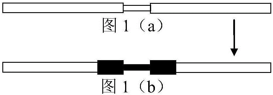
[0022] In order to make the object, technical solution and advantages of the present invention clearer, the present invention will be further described in detail below in conjunction with the accompanying drawings and embodiments. It should be understood that the specific embodiments described here are only used to explain the present invention, not to limit the present invention. In addition, the technical features involved in the various embodiments of the present invention described below can be combined with each other as long as they do not constitute a conflict with each other.

[0023] In the production technology of electronic products, the pros and cons of the soldering process have an important impact on the quality and reliability of the product, and the reflow oven is an important equipment for soldering. Reflow soldering is also called reflow soldering. Reflow soldering is to realize the mechanical connection between the soldering end of the component and the prin...


PUM

PropertyMeasurementUnit
Thicknessaaaaaaaaaa

Abstract

The invention discloses a preparation method for a fiber bragg grating magnetic sensor based on reflow soldering. The method comprises the following steps: 1) selecting silicon wafer with a rectangular shade and ultrasonically cleaning the silicon wafer; 2) sputtering a magnetostrictive film layer with certain thickness on the silicon wafer by a magnetic sputtering method; 3) selecting a fiber bragg grating which can be used under a high-temperature condition and ultrasonically cleaning the fiber bragg grating; 4) sputtering a metal film layer with certain thickness on the fiber bragg grating by the magnetic sputtering method; 5) fixing the fiber bragg grating coated with the metal film to the magnetostrictive film; and 6) adopting the reflux welding method for welding the fiber bragg grating coated with the metal film to the magnetostrictive film, thereby forming a reliable welding point, and establishing long-term mechanical connection between the fiber bragg grating and the magnetostrictive film. The preparation method is simple in process and is convenient to operate; and a manufactured sensor is good in performance.

Description

technical field [0001] The invention belongs to the field of optical fiber grating magnetic sensors, and more particularly relates to a preparation process and connection method of optical fiber grating magnetic sensors. Background technique [0002] The fiber Bragg grating magnetic sensor is a device that realizes the conversion of magnetic signals and optical signals. It uses the magnetostrictive film to generate stretching deformation for the changing magnetic signal, and this deformation will cause the stress change on the magnetostrictive film. Sensitive, this is because the stress change will cause the center wavelength reflected by the fiber Bragg grating to drift, and the sensing of the stress can be realized by measuring the shift of the wavelength, and then the measurement of the magnetic signal can be realized. The key to FBG to realize magnetic signal measurement is the composite method of FBG and magnetostrictive film, which is also a challenge for the applicati...

Claims


Application Information

Patent Timeline
IPC IPC(8): B23K1/20B23K1/00G01L1/24
CPCB23K1/0008B23K1/206B23K2101/36G01L1/242
Inventor 杨晓非李家普欧阳君陈泽基王鲜然李俊宇朱本鹏陈实
Owner HUAZHONG UNIV OF SCI & TECH
Learn More