Manufacturing method of anisotropic optical film

A technology of anisotropy and manufacturing method, applied in the field of manufacturing anisotropic optical films, can solve the problems of easy dazzling, brightness change, easy to produce light interference, etc.

Active Publication Date: 2018-05-29
TOMOEGAWA PAPER CO LTD
View PDF7 Cites 0 Cited by
  • Summary
  • Abstract
  • Description
  • Claims
  • Application Information

AI Technical Summary

Problems solved by technology

Therefore, for an anisotropic optical film with a plate-like structure, for example, when the diffusion width is narrowed in the TD direction, a sharp change in brightness occurs in the TD direction, and as a result, light interference is likely to occur, and it is easy to dazzle.

Method used


Image

  • Manufacturing method of anisotropic optical film
  • Manufacturing method of anisotropic optical film
  • Manufacturing method of anisotropic optical film

Examples


Embodiment

[0135] An anisotropic optical film of the present invention and an anisotropic optical film of a comparative example were produced by the following methods. In addition, in the following content, an anisotropic optical film is a film which consists of only one anisotropic diffusion layer.

[0136]

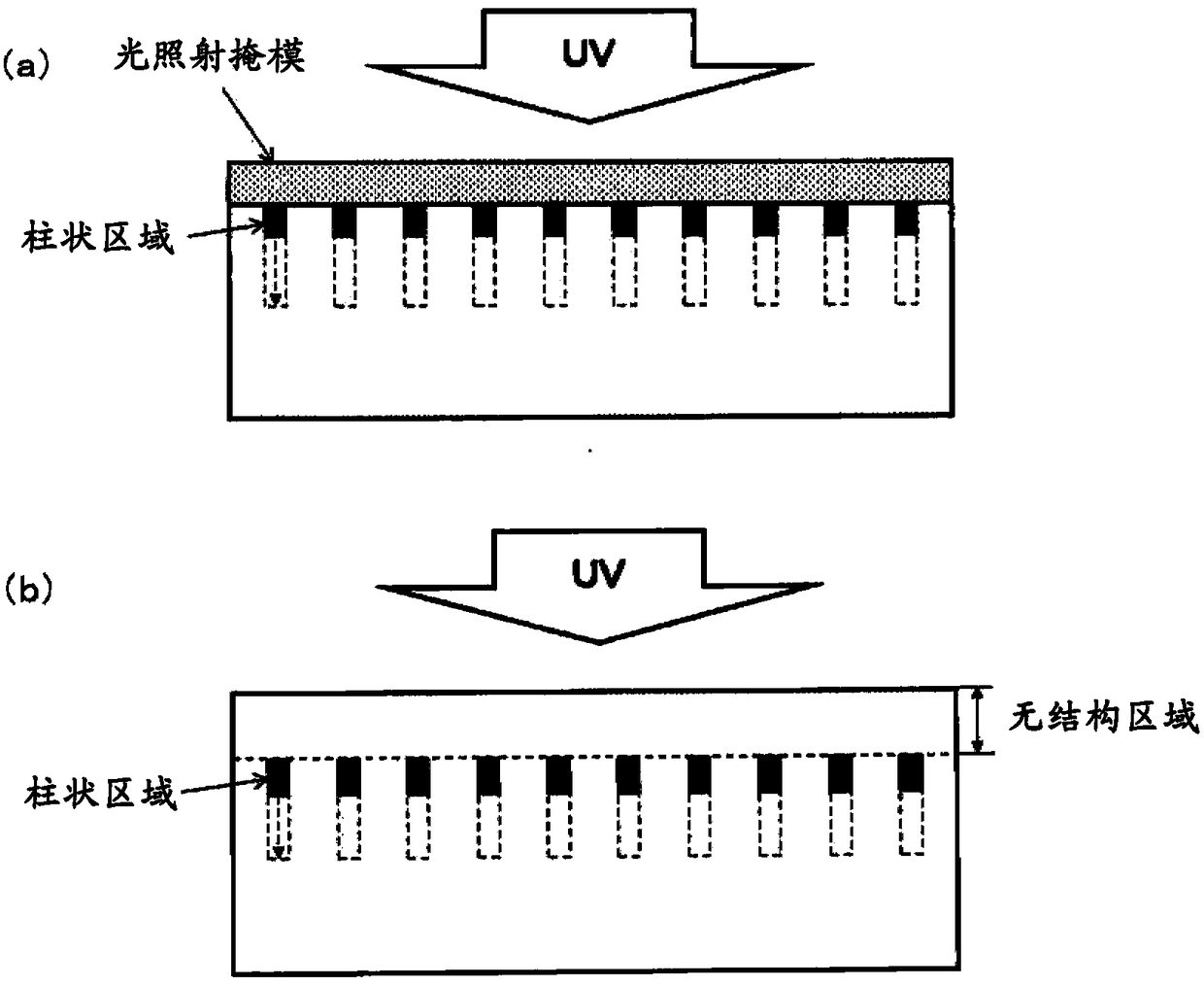
[0137] A PET film with a thickness of 100 μm and a size of 76×26 mm (manufactured by Toyobo Co., Ltd., trade name: A4100, haze=0.5%) was used as the base film, and a photocurable film was applied to the entire periphery of the edge portion using a dispenser. The resin composition forms partition walls. The formed partition walls are shown in Table 1, which differ according to different examples. The height of this partition wall corresponds substantially to the thickness of the obtained anisotropic optical film. The following photocurable resin composition was filled in this partition, and it covered with a UV irradiation mask (photoirradiation mask). However, when the UV irra...


PUM

PropertyMeasurementUnit
particle sizeaaaaaaaaaa
surface roughnessaaaaaaaaaa
thicknessaaaaaaaaaa

Abstract

The present invention provides a method for producing an anisotropic optical film. When producing an anisotropic optical film, by suppressing the formation of a structure-free region, a specific film thickness can be obtained without grinding the structure-free region or the like. Anisotropic optical film with desired optical properties. A method of manufacturing an anisotropic optical film whose diffusivity varies according to the incident angle of light, the method of manufacturing an anisotropic optical film comprising the steps of: A light irradiation mask bonding step of bonding a light irradiation mask having a haze value of 1.0 to 50.0% on one side of the resin composition layer; and after the light irradiation mask bonding step, irradiating through the light irradiation mask Light, so that the uncured resin composition layer is cured to form a curing process of anisotropic diffusion layer.

Description

technical field [0001] The present invention relates to a method for producing an anisotropic optical film whose diffusivity of transmitted light changes according to an incident angle. Background technique [0002] Members having light diffusing properties are used in display devices as well as lighting devices and building materials. As such a display device, there are, for example, a liquid crystal display device (LCD), an organic electroluminescence element (organic EL), and the like. Examples of the light diffusion mechanism of the light diffusion member include diffusion caused by unevenness formed on the surface (surface diffusion), and diffusion caused by the difference in refractive index between the matrix resin and fine particles dispersed therein (internal diffusion). , and the diffusion caused by both surface diffusion and internal diffusion. However, these light diffusing members are generally isotropic in diffusing performance, and even if the incident angle...

Claims


Application Information

Patent Timeline
Patent Type & Authority Patents(China)
IPC IPC(8): B29D7/01B29C33/38B29C48/154
CPCB29C33/3807B29D7/01B29D11/00798G02B2207/123B29C48/154G02B5/0257G02B5/0236G02B5/3066H10K50/86B29D11/00634
Inventor 杉山仁英
Owner TOMOEGAWA PAPER CO LTD
Why Eureka
Try Eureka